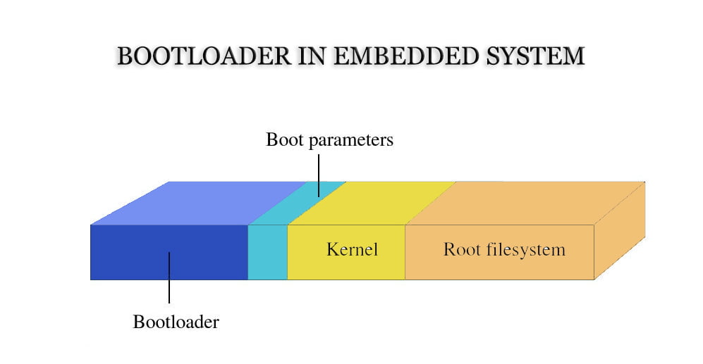
What is a Bootloader?
The Bootloader is the first segment of code executed in an embedded system after power-up. Once it completes the initialization of the CPU and relevant hardware, it loads the operating system image or embedded application program into memory and then transitions to the space where the operating system resides, thus initiating the operation of the operating system. This process is fundamental for anyone involved in programming specific microcontrollers like STM32.
Similar to an application program, A Bootloader is a standalone program that contains essential components such as startup code, interrupts, a main program (Boot_main function), and optionally, an operating system. Despite its small size, the Bootloader encompasses critical functionalities.
Bootloaders are typically heavily reliant on hardware and are especially significant in the realm of embedded systems. As a result, creating a universally applicable bootloader in the embedded domain is nearly impossible. Nevertheless, we can still generalize some concepts about bootloaders to guide users in designing and implementing specific bootloaders.
Operation Modes of a Bootloader
Most bootloaders comprise two distinct operation modes: the boot mode and the download mode.
Upon power-up, the bootloader initializes the system’s software and hardware environment and selects one of the operation modes based on the current hardware conditions. This involves configuring the CPU operation mode, initializing memory, disabling interrupts, and handling tasks like turning off the MMU/Cache.
Boot Loading Mode:
This mode, also known as the “autonomous” mode, involves the Boot Loader autonomously loading the operating system from a solid-state storage device on the target machine into RAM. This entire process occurs without any user intervention. This mode represents the normal operation of the Boot Loader.
Download Mode:
In this mode, the Boot Loader on the target machine initiates communication through means such as serial or network connections with a host machine to download files. Files obtained from the host machine are typically stored in the RAM of the target machine by the Boot Loader before being written into the Flash memory or similar solid-state storage device on the target machine.
How Does a Bootloader Work?
There’re two types of startup process for a Bootloader: Single-Stage and Multi-Stage. Generally, multi-stage Boot Loaders possess more complex functionalities and enhanced portability. Boot Loaders that initiate from solid-state storage devices often use a two-stage process, divided into stage 1 and stage 2: stage 1 performs hardware initialization, prepares memory space for stage 2, copies stage 2 to memory, sets up the stack, and then transitions to stage 2.
Bootloader Stage 1
Hardware Device Initialization
- Disable All Interrupts: Handling interrupts is typically the responsibility of OS device drivers, so Boot Loader can disregard interrupt responses throughout its execution. Interrupt masking can be achieved by modifying the CPU’s interrupt mask register or status register (such as ARM’s CPSR register).
- Set CPU Speed and Clock Frequency.
- Initialize RAM: This encompasses correctly configuring the system’s memory controller’s function registers and various memory bank control registers.
- LED Initialization: LEDs are often driven through GPIO to indicate the system’s status (OK or Error). If LEDs are absent, initialization of UART to print the Boot Loader’s logo or character information via serial communication can serve this purpose.
- Disable CPU Internal Instruction/Data Cache.
Prepare RAM Space for Loading Bootloader Stage 2
For faster execution, stage 2 is commonly loaded into RAM. Therefore, an available memory range must be allocated for loading Boot Loader’s stage 2.
Since stage 2 usually contains C language code, the space required must consider both the executable size of stage 2 and stack space. Additionally, the space should preferably align with memory page size (typically 4KB). Generally, 1MB of RAM space is sufficient. The specific address range can be chosen arbitrarily. For instance, a common approach is to allocate stage 2’s executable image to execute within a 1MB space starting from the system RAM’s base address of 0xc0200000. However, allocating stage 2 to the uppermost 1MB of the entire RAM space (i.e., (RamEnd-1MB) – RamEnd) is a recommended strategy.
Let’s denote the allocated RAM space range size as “stage2_size” (in bytes), and the start and end addresses as “stage2_start” and “stage2_end” (both addresses aligned to 4-byte boundaries). Thus:
stage2_end = stage2_start + stage2_size
Furthermore, it’s imperative to ensure that the allocated address range is indeed writable and readable RAM space. To ensure this, testing of the allocated address range is necessary. A suitable testing method, like the one used by “blob,” involves testing each memory page’s first two words for read-write capability.
Copy Boot Loader's Stage 2 to RAM Space
To do this, please ensure two points:
- The executable image of stage 2’s location on the solid-state storage device.
- The start address of RAM space.
Set Stack Pointer (SP)
Setting the stack pointer (sp) prepares for executing C language code. Typically, sp’s value can be set to (stage2_end-4), representing the topmost end of the 1MB RAM space allocated in section 3.1.2 (stack grows downward).
Additionally, before setting the stack pointer, it’s possible to deactivate the LED as a signal to users that a transition to stage 2 is imminent.
Following these execution steps, the system’s physical memory layout should resemble the diagram below.

Jump to the C entry point of stage2
After everything above is ready, you can jump to stage2 of Boot Loader to execute. For example, on ARM systems this can be done by modifying the PC register to the appropriate address. The system memory layout when the stage2 executable image of the bootloader has just been copied to the RAM space is shown in the figure above.
Bootloader Stage 2
Hardware Device Initialization
- Initialize at least one serial port for I/O output communication with terminal users.
- Initialize timers and other hardware components.
Before initializing these devices, it’s also possible to illuminate the LED to indicate the commencement of executing the main() function. After device initialization, certain information such as program name strings and version numbers can be output.
System Memory Mapping Detection
Memory mapping refers to the allocation of address ranges within the entire 4GB physical address space for addressing system RAM units. For instance, in the SA-1100 CPU, a 512MB address space starting from 0xC000,0000 serves as the system’s RAM address space. In the case of the Samsung S3C44B0X CPU, a 64MB address space between 0x0c00,0000 and 0x1000,0000 is used for the system’s RAM address space. While CPUs typically reserve a substantial portion of address space for system RAM, not all the reserved RAM address space may be utilized when constructing specific embedded systems. Thus, embedded systems often map only a portion of the CPU’s reserved RAM address space to RAM units, leaving some of the reserved RAM address space unused. Given this fact, Boot Loader’s stage 2 must examine the entire system’s memory mapping before attempting any actions (such as reading a kernel image stored in flash to RAM space). It needs to know which parts of the CPU’s reserved RAM address space are genuinely mapped to RAM address units and which are in an “unused” state.
Description of Memory Mapping
The following data structure can be used to describe a continuous address range in the RAM address space:
					typedef struct memory_area_struct {
    u32 start; /* the base address of the memory region */
    u32 size; /* the byte number of the memory region */
    int used;
} memory_area_t;
Such contiguous address ranges within the RAM address space can be in one of two states:
- used=1 indicates that the continuous address range has been implemented and is genuinely mapped to RAM units.
- used=0 indicates that the continuous address range is not implemented in the system and remains unused.
Based on the memory_area_t data structure described above, the entire CPU’s reserved RAM address space can be represented by an array of memory_area_t type, as shown below:
					memory_area_t memory_map[NUM_MEM_AREAS] = {
    [0 ... (NUM_MEM_AREAS - 1)] = {
        .start = 0,
        .size = 0,
        .used = 0
    },
};
Memory Mapping Detection
Here’s a simple yet effective algorithm to detect the memory mapping situation within the entire RAM address space:
					/* Initialize the array */
for(i = 0; i < NUM_MEM_AREAS; i++)
    memory_map[i].used = 0;
/* Write 0 to all memory locations */
for(addr = MEM_START; addr < MEM_END; addr += PAGE_SIZE)
    *(u32 *)addr = 0;
for(i = 0, addr = MEM_START; addr < MEM_END; addr += PAGE_SIZE) {
    /*
     * Check whether the address space starting from base address
     * MEM_START + i * PAGE_SIZE, with a size of PAGE_SIZE, is a valid RAM address space.
     */
    Call the algorithm test_mempage() from section 3.1.2;
    if (current memory page is not a valid RAM page) {
        /* no RAM here */
        if (memory_map[i].used )
            i++;
        continue;
    }

    /*
     * The current page is a valid address range mapped to RAM.
     * However, we need to determine if it's an alias of some address page within the 4GB address space.
     */
    if (*(u32 *)addr != 0) { /* alias? */
        /* This memory page is an alias of an address page within the 4GB address space. */
        if (memory_map[i].used )
            i++;
        continue;
    }

    /*
     * The current page is a valid address range mapped to RAM,
     * and it's not an alias of an address page within the 4GB address space.
     */
    if (memory_map[i].used == 0) {
        memory_map[i].start = addr;
        memory_map[i].size = PAGE_SIZE;
        memory_map[i].used = 1;
    } else {
        memory_map[i].size += PAGE_SIZE;
    }
} /* end of for (…) */
Upon executing the above algorithm to detect the memory mapping status of the system, the Boot Loader can also print detailed memory mapping information to the serial port.
Loading Kernel and Root File System Images
Memory Layout Planning
This involves two aspects:
- the memory range occupied by the kernel image;
- the memory range occupied by the root file system. When planning the memory layout, consider the base address and the size of the images.
For the kernel image, it’s common to copy it to a memory range starting from (MEM_START + 0x8000), approximately 1MB in size (embedded Linux kernels are usually under 1MB). Why leave a 32KB space from MEM_START to MEM_START + 0x8000? This is because the Linux kernel places certain global data structures in this memory segment, such as boot parameters and kernel page tables.
For the root file system image, it’s generally copied to the location starting from MEM_START + 0x0010,0000. If using a Ramdisk as the root file system image, the uncompressed size is typically around 1MB.
Copying from Flash
Since embedded CPUs like ARM usually address Flash and other solid-state storage devices within a unified memory address space, reading data from Flash is similar to reading from RAM units. A simple loop suffices to copy the image from the Flash device:
					while (count) {
    *dest++ = *src++; /* they are all aligned with word boundary */
    count -= 4; /* byte number */
};
Setting Kernel Boot Parameters
After copying the kernel image and root file system image to RAM space, Linux kernel startup can be prepared. But before invoking the kernel, a preparation step is necessary: setting the Linux kernel’s boot parameters.
Linux kernels from version 2.4.x onwards expect boot parameters to be passed in the form of a tagged list. The boot parameter tagged list begins with the tag ATAG_CORE and ends with the tag ATAG_NONE. Each tag consists of a tag_header structure identifying the parameter, followed by data structures containing parameter values. The data structures tag and tag_header are defined in the include/asm/setup.h header file of the Linux kernel source code.
In embedded Linux systems, common boot parameters that need to be set by the Boot Loader include ATAG_CORE, ATAG_MEM, ATAG_CMDLINE, ATAG_RAMDISK, and ATAG_INITRD.
For instance, here’s how to set ATAG_CORE:
					params = (struct tag *)BOOT_PARAMS;
params->hdr.tag = ATAG_CORE;
params->hdr.size = tag_size(tag_core);
params->u.core.flags = 0;
params->u.core.pagesize = 0;
params->u.core.rootdev = 0;
params = tag_next(params);
Here, BOOT_PARAMS represents the starting base address of kernel boot parameters in memory, and the pointer params is of type struct tag. The macro tag_next() calculates the starting address of the next tag immediately following the current tag. It’s important to note that the device ID for the kernel’s root file system is set here.
Below is an example code for setting memory mapping information:
					for (i = 0; i < NUM_MEM_AREAS; i++) {
    if (memory_map[i].used) {
        params->hdr.tag = ATAG_MEM;
        params->hdr.size = tag_size(tag_mem32);
        params->u.mem.start = memory_map[i].start;
        params->u.mem.size = memory_map[i].size;
        params = tag_next(params);
    }
}
In the memory_map[] array, each valid memory segment corresponds to an ATAG_MEM parameter tag.
The Linux kernel can receive information as command-line parameters during startup. This allows us to provide hardware parameter information that the kernel cannot detect itself or override information that the kernel has detected. For instance, we use the command-line parameter string “console=ttyS0,115200n8” to instruct the kernel to use ttyS0 as the console with settings “115200bps, no parity, 8 data bits.” Here’s an example code to set the kernel’s command-line parameter string:
					char *p;
for (p = commandline; *p == ' '; p++)
    ;
if (*p == '\0')
    return;
params->hdr.tag = ATAG_CMDLINE;
params->hdr.size = (sizeof(struct tag_header) + strlen(p) + 1 + 4) >> 2;
strcpy(params->u.cmdline.cmdline, p);
params = tag_next(params);
Note that in the above code, when setting the size of tag_header, it must include the terminating ‘\0’ character in the string and be rounded up to the nearest multiple of 4 bytes, as the size member of tag_header structure represents the number of words.
Below is an example code for setting ATAG_INITRD, indicating the location in RAM where the initrd image (in compressed format) can be found, along with its size:
					params->hdr.tag = ATAG_INITRD2;
params->hdr.size = tag_size(tag_initrd);
params->u.initrd.start = RAMDISK_RAM_BASE;
params->u.initrd.size = INITRD_LEN;
params = tag_next(params);
Finally, set the ATAG_NONE tag to conclude the entire list of startup parameters:
					static void setup_end_tag(void) {
    params->hdr.tag = ATAG_NONE;
    params->hdr.size = 0;
}
Invoking the Kernel
The Boot Loader calls the Linux kernel by directly jumping to the first instruction of the kernel, i.e., directly jumping to the address MEM_START + 0x8000. The following conditions need to be met when jumping:
- CPU register settings:
R0 = 0
R1 = Machine type ID (for Machine Type Number, refer to linux/arch/arm/tools/mach-types)
R2 = Starting base address of the boot parameter tagged list in RAM - CPU mode:
Disable interrupts (IRQs and FIQs)
CPU must be in SVC mode - Cache and MMU settings:
MMU must be turned off
Instruction cache can be on or off
Data cache must be turned off
If using C, invoking the kernel can be done like this:
					void (*theKernel)(int zero, int arch, u32 params_addr) =
    (void (*)(int, int, u32))KERNEL_RAM_BASE;

theKernel(0, ARCH_NUMBER, (u32)kernel_params_start);
Note that the function call to theKernel() should never return. If it returns, an error has occurred.
Embedded System BootLoader Vs PC Bootloader
In PC architectures, the bootloader consists of the BIOS (essentially firmware) and the OS bootloader located in the hard disk’s MBR (e.g., LILO, GRUB). After BIOS completes hardware detection and resource allocation, it loads the bootloader from the hard disk’s MBR into the system’s RAM and hands control to the OS bootloader. The primary task of the bootloader is to read the kernel image from the hard disk into RAM and then jump to the kernel’s entry point to start the operating system.
In embedded systems, there is typically no firmware program like BIOS (although some embedded CPUs might include a small embedded boot program). Consequently, the entire system’s loading and startup task is carried out by the bootloader. For instance, in an embedded system based on the ARM7TDMI core, the system typically starts execution at address 0x00000000 during power-on or reset, and this address usually contains the system’s bootloader program.
CPU and Embedded Board supported by Boot Loader
Each different CPU architecture has a different Boot Loader. Some Boot Loaders also support CPUs with multiple architectures. For example, U-Boot supports both ARM architecture and MIPS architecture. In addition to relying on the architecture of the CPU, Boot Loader actually also depends on the configuration of specific embedded board-level devices. That is to say, the Boot Loader is not necessarily suitable for both the two different embedded boards, even if they are built based on the same CPU.
Bootloader Installation Medium
When a system powers on or resets, CPUs usually fetch instructions from a predetermined address set by the CPU manufacturer. For example, CPUs based on the ARM7TDMI core usually fetch their first instruction from address 0x00000000 after a reset. Embedded systems built upon CPU architectures often map some type of solid-state storage device (such as ROM, EPROM, or FLASH) to this predetermined address. Therefore, after system power-on, the CPU first executes the bootloader program.
Engineering Checklist for how to write a bootloader for microcontroller
When using how to write a bootloader for microcontroller as a design or troubleshooting reference, connect the search topic to real board constraints. The key is to verify the electrical, mechanical, and documentation details before changing a circuit or drawing conclusion from a single symptom.
- Confirm the design context: Review boot sequence, vector table, flash layout, update interface, rollback plan, and code-protection state.
- Check the board evidence: Compare markings, measurements, connector orientation, supply rails, and nearby support components.
- Validate with measurements: Use controlled power, continuity checks, voltage/current readings, and waveform inspection where relevant.
- Document the result: Save photos, test conditions, calculated values, and any replacement-part assumptions for repeatable PCB repair or reverse engineering work.
This practical checklist helps turn the search intent behind how to write a bootloader for microcontroller into actionable PCB-level analysis.