the ATtiny85 microcontroller stands tall as a powerful yet compact device that has revolutionized the field of electronics. With its small size and impressive capabilities, the ATtiny85 has become a go-to choice for hobbyists, engineers, and innovators alike. In this post, we’ll introduce the features of the ATtiny85 microcontroller, it’s pinout, specifications, applications and programming tutorial.
Introducing the ATtiny85 microcontroller
The ATtiny85 microcontroller, is a member of the AVR family of microcontrollers developed by Atmel Corporation. It is based on the AVR RISC architecture, which stands for Reduced Instruction Set Computer. This architecture is known for its simplicity and efficiency, making it ideal for low-power applications. With its 8-bit processing power and a clock speed of up to 20 MHz, the ATtiny85 can handle a wide range of tasks, including digital signal processing, data acquisition, and control algorithms. Its small form factor, low power consumption, and affordability make it a popular choice among hobbyists and professionals alike.
ATtiny85 Pinout
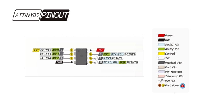
| Pin Number | Pin Name | Function |
|---|---|---|
| 1 | PB5 / RESET | Digital I/O / Reset |
| 2 | PB3 / PWM | Digital I/O / PWM |
| 3 | PB4 / PWM | Digital I/O / PWM |
| 4 | GND | Ground |
| 5 | PB0 / ADC | Digital I/O / Analog-to-Digital Converter (ADC) |
| 6 | PB1 / ADC | Digital I/O / ADC |
| 7 | PB2 / ADC | Digital I/O / ADC |
| 8 | VCC | Positive Supply Voltage |
ATtiny85 Features
- AVR RISC architecture
- Low power consumption
- Easy integration with external modules
- Built-in analog-to-digital converter (ADC)
- Supports pulse-width modulation (PWM) for analog outputs
- Supports in-circuit serial programming (ISP) via the SPI interface
ATtiny85 Specifications
The ATtiny85 microcontroller boasts an impressive set of specifications that make it an attractive choice for various projects.
| Parameter | Value |
|---|---|
| Manufacturer | Microchip |
| Family | tinyAVR |
| Flash | 8 kB |
| SRAM | 512 bytes |
| EEPROM | 512 bytes |
| ADC Counts | 10 bit |
| Speed | 20 MHz |
| I/O | 6 |
| RAM | 512 B |
| Voltage | 1.8 V to 5.5 V |
| Temperature | -40 ℃ to +85 ℃ |
| PWM | 4 |
| Timer Counts | 2 |
| Package | SOIC-8 or PDIP-8 |
| Size | 5.35 * 5.40 * 2.16 mm |
ATtiny85 Applications
- Wearable technology: smartwatches, fitness trackers, and health monitoring devices.
- Industrial Automation: monitoring and controlling temperature, pressure.
- Home automation: lighting, temperature control, and security systems.
- Educational projects: teach programming, electronics, and robotics.
- Sensor Nodes: temperature, humidity, light, and motion sensors.
- Environmental Monitoring: air quality, pollution levels, or weather parameters.
- Security Systems: door/window sensors, motion detectors, or alarm systems.
- Smart Agriculture: soil moisture, temperature, and other environmental factors.
How to Program An Attiny85 with Arduino IDE?
Required parts:
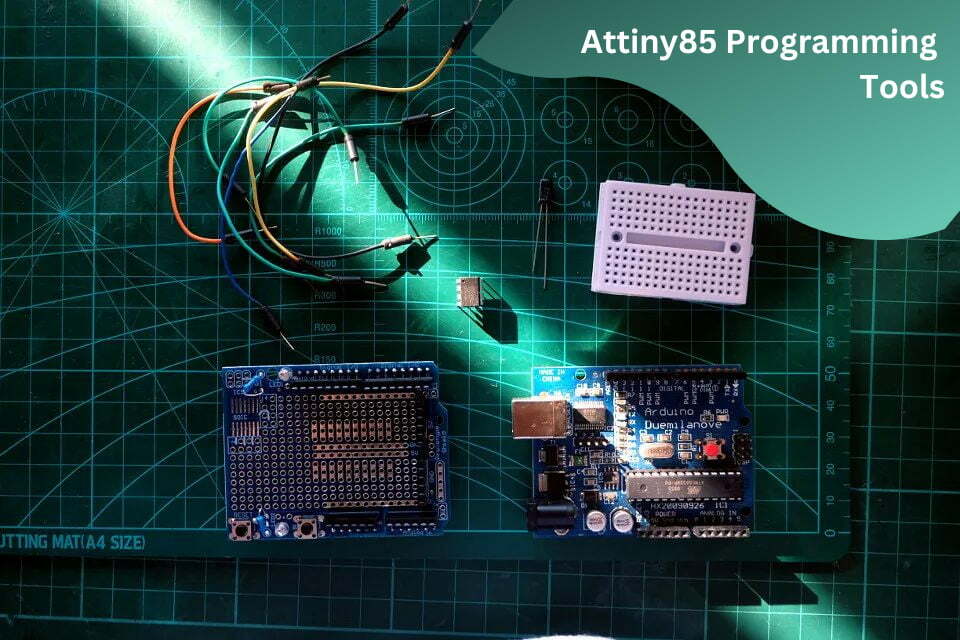
- Arduino Duemilanove development board (chip needs to be ATmega328) x1
- ATtiny85 microprocessor x1
- 10uf capacitor x1
- Several jumpers
- Breadboard or Duemilanove compatible prototype shield x1
Step 1. Set up the Program Uploader
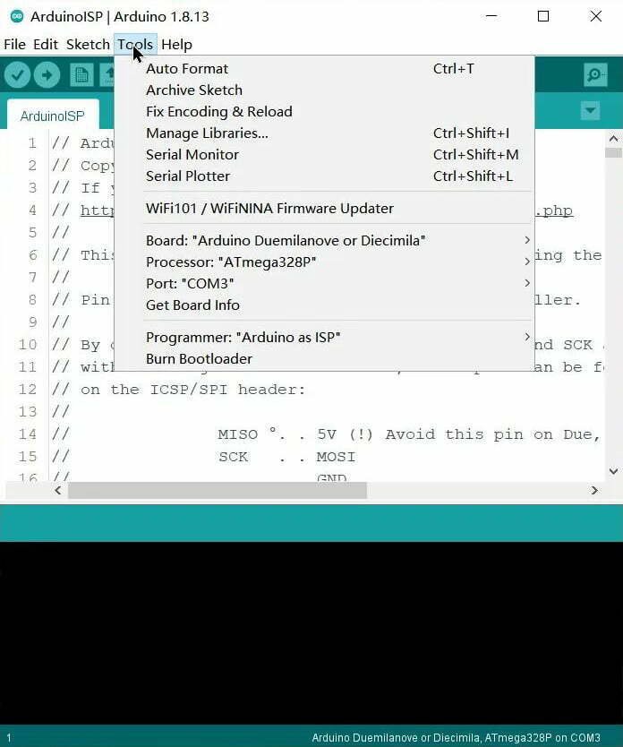
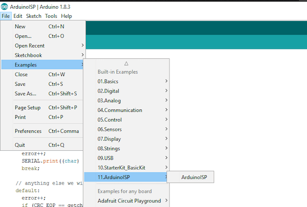
- The Arduino Duemilanove development board is connected to the computer with a USB cable;
- Open the Arduino IDE software (version 1.6 or above);
- Select the development board and the corresponding serial port under the Tools option;
- Select Arduino ISP under File–>Examples;
- Click Upload.
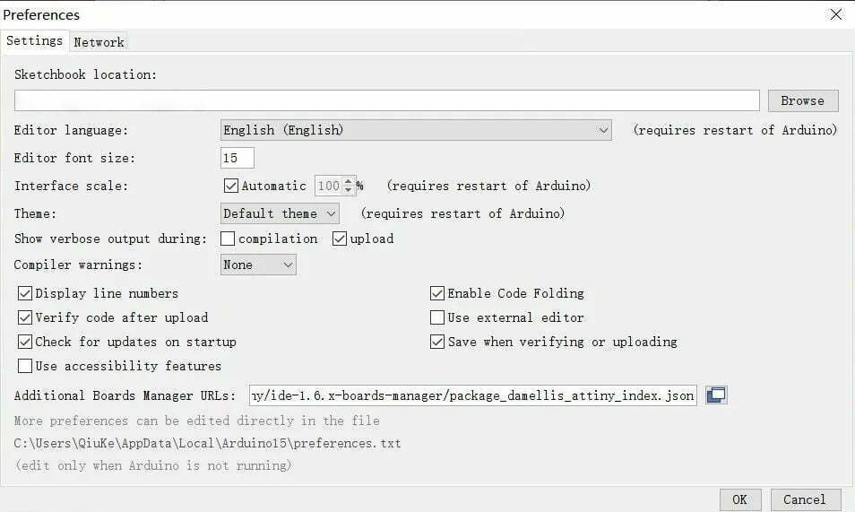
Step 2. Configure Arduino IDE
In the Arduino IDE software, go to File–>Preferences, click the text box behind “Additional Board Managers URLs:”, and modify the URL to: https://raw.githubusercontent.com/damellis/attiny/ide-1.6.x -boards-manager/package_damellis_attiny_index.json, click OK;
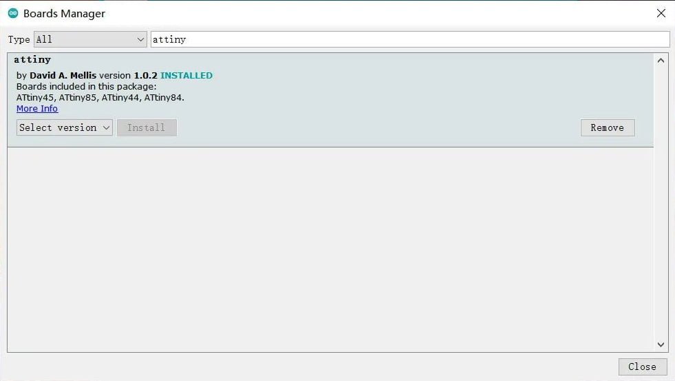
Click Tools–>Board–>Boards Manager in turn, enter attiny in the search box, find the ATtiny Boards and install it.
Step 3. Connect ATtiny85 and Arduino Duemilanove
Connect ATtiny85 and Duemilanove according to the circuit diagram below:
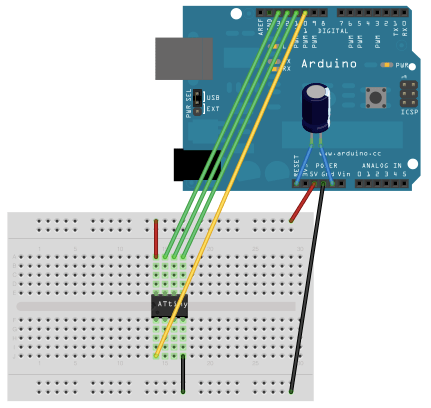
The positive pole of the 10uf capacitor is connected to RESET of the Duemilanove development board, and the negative pole is connected to GND. The pin connections between ATtiny85 and Arduino Duemilanove are as follows:
Pin connection between ATtiny85 and Arduino Duemilanove
| ATtiny85 | Arduino Duemilanove |
|---|---|
| Pin 1 (RESET) | Pin 10 |
| Pin 4 (GND) | GND |
| Pin 5 | Pin 11 |
| Pin 6 | Pin 12 |
| Pin 7 | Pin 13 |
| Pin 8 | 5V |
Step 4. Programming and uploading
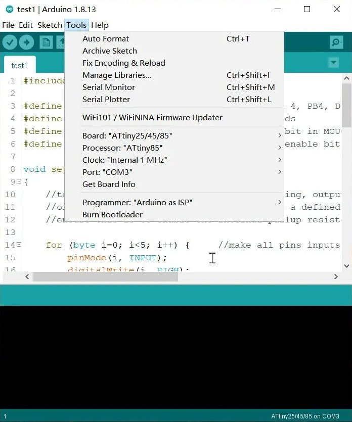
Open the Arduino software, select ATtiny25/45/85 under Tools–>Board, select ATtiny85 for Proccesor, keep the port unchanged, select Arduino as ISP for the programmer, and then you can write the program and upload it to the ATtiny85.
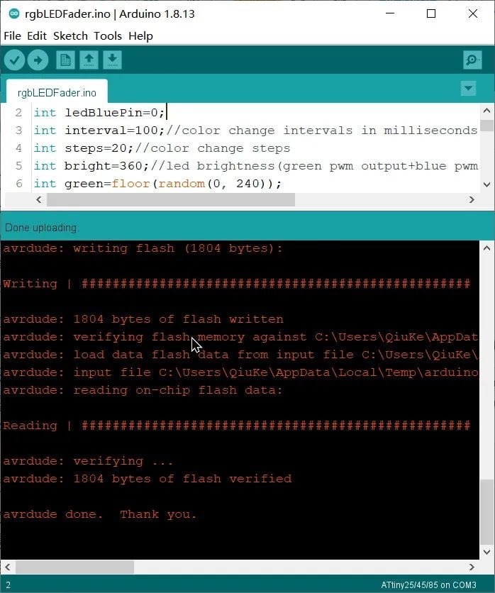
If the words “avrdude done. Thank you.” appear after uploading, it means the uploading is successful. After unplugging the USB cable, take the ATtiny85 off the breadboard and connect it to the actual circuit to complete the production.


