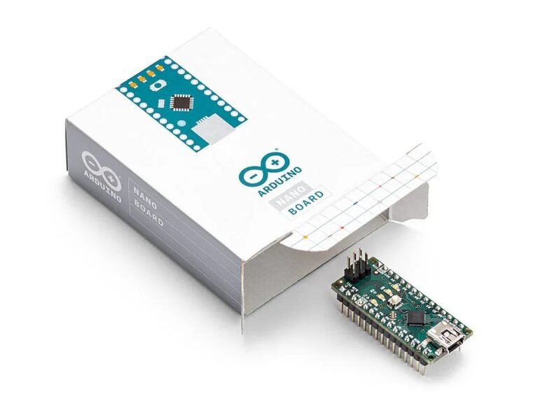
The Arduino Nano is a popular choice for makers, hobbyists, and engineers who need a capable microcontroller for their electronic projects. It comes with small footprint and flexibility. Whether you’re building a simple sensor-based application or a more complex IoT device, the Arduino Nano provides all the essential features in a portable, easy-to-use package. In this article, we’ll introduce its’ features, specifications, pinout, and programming tutorials.
What is An Arduino Nano?
The Arduino Nano is a compact, versatile microcontroller board that packs a punch despite its small size. Designed to fit in tight spaces, it’s an ideal choice for projects where size matters, such as wearable devices, robotics, and embedded systems. Based on the ATmega328P microcontroller (on the Nano 3.0), the Nano offers 14 digital I/O pins (6 of which can generate PWM output), 8 analog inputs, and a 16 MHz clock speed. Unlike larger Arduino boards, it connects via a Mini-B USB port, making it perfect for breadboard-based prototyping without the need for additional hardware.
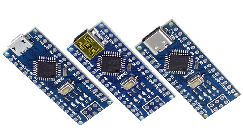
Key Features and Specifications
- Processor: ATmega328P (Nano 3.0 version)
- Operating Voltage: 5V
- Recommended Input Voltage: 7–12V
- Input Voltage Range: 6–20V
- Digital I/O Pins: 14 (6 of which can be used for PWM output)
- Analog Input Pins: 8
- DC Current per I/O Pin: 40mA
- Flash Memory: 32KB
- SRAM: 2KB
- EEPROM: 1KB
- Clock Speed: 16 MHz
- USB Interface: Mini-B USB port for programming and communication
pin configuration of arduino nano
The Arduino Nano features a total of 32 pins, with multiple functions assigned to each. These pins are grouped into three main ports: PortB, PortC, and PortD. Here is a breakdown of the important pins and their functionality:

- Pin 1 (RX) and Pin 2 (TX): These are serial communication pins, used for receiving and transmitting data between the Nano and a host computer. The Nano uses the CH340 chip to convert USB signals into TTL serial data.
- Pin 3: Reset pin, used for resetting the microcontroller.
- Pin 4: Ground pin (GND).
- Pins 5–16: Digital I/O pins; pins 5 and 6 are also external interrupt pins.
- Pin 17: 3.3V power output from the CH340 USB chip, useful for powering 3.3V systems.
- Pin 18: AREF (Analog Reference), used for analog-to-digital conversions. Typically, this pin is unused unless you want to provide an external reference voltage.
- Pins 19–26: Analog input pins (A0 to A7).
- Pin 27: Bidirectional power pin, used for supplying 5V to external devices or accepting input from an external 5V power source.
- Pin 28: System reset pin.
- Pin 29: Ground pin (GND).
- Pin 30: External power input (Vin), typically used when providing external power through a battery or DC adapter.
Arduino Nano Models
There are several variations of the Arduino Nano, each suited for different types of projects. Here’s a look at the key models and their specifications:
Arduino Nano ESP32
The Arduino Nano ESP32 is a powerful board based on the ESP32 microcontroller, offering dual-core processing, more memory, and integrated wireless capabilities (Wi-Fi and Bluetooth), making it suitable for IoT applications and more demanding projects.

| Specification | Details |
|---|---|
| Microcontroller | ESP32 (Dual-core 32-bit) |
| Clock Speed | 240 MHz |
| Flash Memory | 4 MB |
| SRAM | 520 KB |
| EEPROM | None |
| USB Interface | Micro-USB |
| Wireless Connectivity | Wi-Fi, Bluetooth |
| Special Features | Built for IoT applications, includes Wi-Fi and Bluetooth 4.2, more processing power, ideal for high-performance projects |
Arduino Nano RP2040 Connect
The Nano RP2040 Connect is designed for IoT applications, featuring Wi-Fi and Bluetooth support with the integrated Nina W102 ESP32 chip. It is ideal for connected devices and remote sensing.
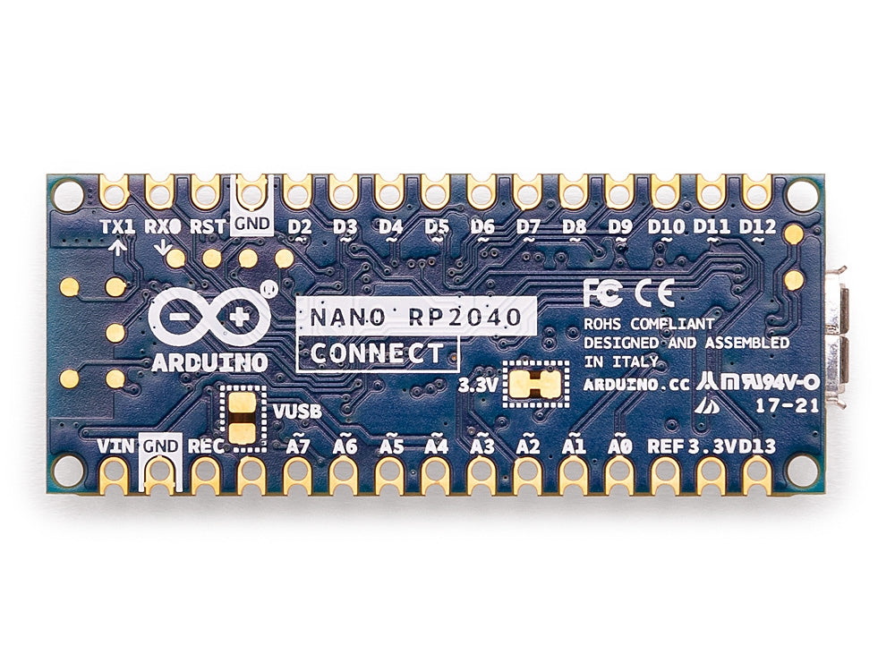
| Specification | Details |
|---|---|
| Microcontroller | Raspberry Pi RP2040 |
| Clock Speed | 133 MHz |
| Flash Memory | 16 MB Flash (external) |
| SRAM | 264 KB |
| EEPROM | None |
| Power Input | 5V via USB or external 5V input |
| Digital I/O Pins | 22 (3 PWM) |
| USB Interface | Micro-USB |
| Wireless Connectivity | Wi-Fi, Bluetooth (Nina W102 uBlox ESP32) |
| Special Features | Built for IoT, includes uBlox Nina W102 chip, ideal for wireless applications |
Arduino Nano Every
The Nano Every offers more memory and I/O capabilities compared to the standard Nano, making it suitable for more advanced projects. It retains compatibility with the classic Nano form factor.

| Specification | Details |
|---|---|
| Microcontroller | Microchip ATMega4809 |
| Clock Speed | 20 MHz |
| Operating Voltage | 5V |
| Digital I/O Pins | 14 |
| Flash Memory | 48 KB |
| SRAM | 6 KB |
| EEPROM | 256 Bytes |
| USB Interface | Micro-USB |
| Wireless Connectivity | None |
| Special Features | Compatible with Arduino Nano form factor, improved memory, and speed |
Arduino Nano 33 IoT
The Nano 33 IoT is equipped with wireless connectivity (Wi-Fi and Bluetooth) and is designed for IoT applications. It also includes a 6-axis accelerometer and gyroscope, making it ideal for projects that involve motion sensing.

| Specification | Details |
|---|---|
| Microcontroller | Microchip SAMD21G18A (Cortex-M0+) |
| Clock Speed | 48 MHz |
| Flash Memory | 256 KB |
| SRAM | 32 KB |
| EEPROM | None |
| Operating Voltage | 3.3V |
| Digital I/O Pins | 14 |
| USB Interface | Micro-USB |
| Wireless Connectivity | Wi-Fi, Bluetooth (Nina W102 ESP32) |
| Special Features | Built for IoT, includes NINA W102 module, sensors, hardware encryption |
Arduino Nano 33 BLE
The Nano 33 BLE offers low-power Bluetooth connectivity, making it ideal for wearable devices, health sensors, and other Bluetooth-based applications. It also features advanced sensors such as a 9-axis accelerometer, gyroscope, and magnetometer.

| Specification | Details |
|---|---|
| Microcontroller | Nordic nRF52840 (Cortex-M4F) |
| Clock Speed | 64 MHz |
| Flash Memory | 1 MB |
| SRAM | 256 KB |
| Operating Voltage | 3.3V |
| Digital I/O Pins | 14 |
| USB Interface | Micro-USB |
| Wireless Connectivity | Bluetooth 5.0 (U-blox NINA B306 module) |
| Special Features | Low power consumption, suitable for wearables, includes 9-axis sensor |
Arduino Nano 33 BLE Sense
The Nano 33 BLE Sense is similar to the Nano 33 BLE but comes with additional onboard sensors, including temperature, humidity, pressure, light, color, gesture recognition, and a digital microphone. This makes it perfect for sensor-heavy applications, including environmental monitoring and wearables.
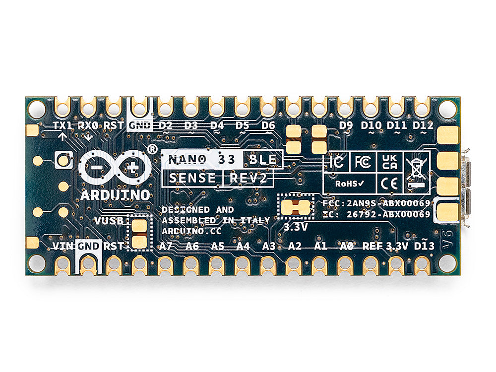
| Specification | Details |
|---|---|
| Microcontroller | Nordic nRF52840 (Cortex-M4F) |
| Clock Speed | 64 MHz |
| Flash Memory | 1 MB |
| SRAM | 256 KB |
| Operating Voltage | 3.3V |
| Digital I/O Pins | 14 |
| USB Interface | Micro-USB |
| Wireless Connectivity | Bluetooth 5.0 (U-blox NINA B306 module) |
| Special Features | Includes additional sensors for temperature, pressure, humidity, light, and gesture recognition |
Programming the Arduino Nano
The Arduino Nano can be programmed using the Arduino IDE, just like other Arduino boards. It comes preloaded with a bootloader, meaning you don’t need an external programmer to upload code.
Step 1: Install the Arduino IDE
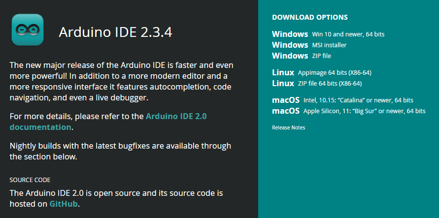
Download the Arduino IDE:
Go to the official Arduino website and download the latest version of the Arduino IDE suitable for your operating system (Windows, macOS, or Linux).
- Install the IDE:
Follow the installation instructions for your operating system. After installation, launch the Arduino IDE.
Step 2: Add ATtiny board to Arduino IDE
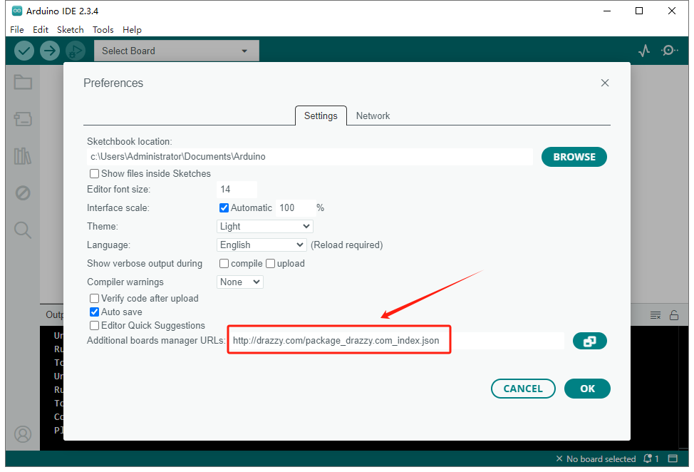
Arduino IDE does not support ATtiny85 by default, so you need to add ATtiny board in Arduino IDE. Open File->Preferences and enter in Additional boards manager URLs:
http://drazzy.com/package_drazzy.com_index.json
Step 3: Select Your Arduino Nano Board and Port
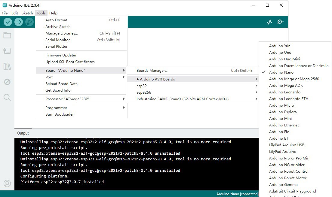
Select the Arduino Nano Board:
- Go to the
Toolsmenu at the top of the IDE. - Select
Board>Arduino Nano. - If you’re using a specific version of the Nano (such as the Nano Every or Nano 33 IoT), select the appropriate version from the list.
- Go to the
Select the Correct Processor:
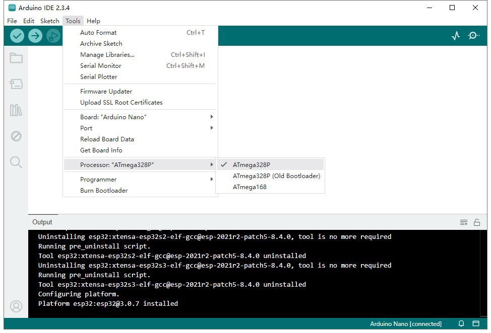
- Still in the
Toolsmenu, go toProcessor. - For the standard Arduino Nano (ATmega328P), select
ATmega328P. If you’re using a newer Nano model like theArduino Nano Every, select the corresponding processor.
- Still in the
Select the Serial Port:
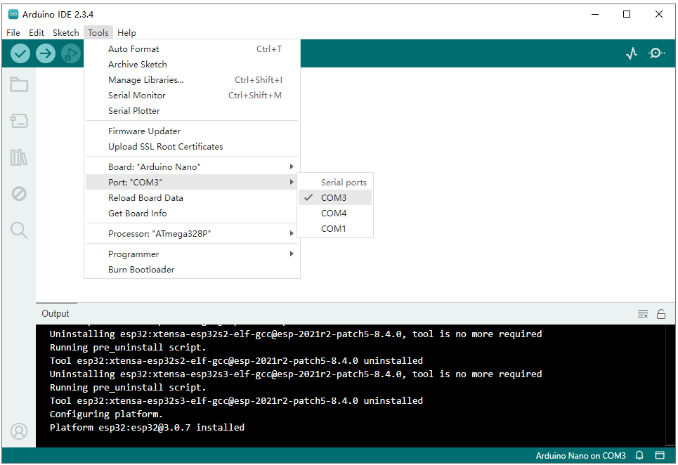
- Under the
Toolsmenu, go toPortand select the port to which your Arduino Nano is connected. On most systems, the Arduino will show up as something likeCOM3(Windows) or/dev/ttyUSB0(Linux/macOS).
- Under the
Install Necessary Drivers (optional):
If you’re using the Arduino Nano 3.0 with the CH340 USB-to-Serial chip, you may need to install additional drivers for your system to recognize the Nano correctly.
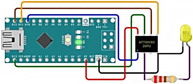
Step 4: Connect ATtiny85 to Arduino Nano
| ATtiny85 Pin | Arduino Nano Pin |
|---|---|
| Pin 8 (VCC) | 5V |
| Pin 4 (GND) | GND |
| Pin 1 (RESET) | D10 |
| Pin 5 (MOSI) | D11 |
| Pin 6 (MISO) | D12 |
| Pin 7 (SCL) | D13 |
Step 5: Write Your First Program
Once everything is set up, you can start writing your code. Here’s an example of the classic “Blink” program that makes an LED connected to pin 13 blink on and off.
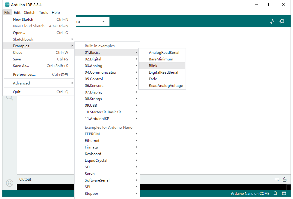
Open the File menu and select Examples > 01.Basics > Blink. This will load a simple program that blinks an LED.
And then add the code like this:
					void setup() {
  pinMode(13, OUTPUT);  // Set pin 13 as an output
}

void loop() {
  digitalWrite(13, HIGH);  // Turn the LED on
  delay(1000);              // Wait for one second
  digitalWrite(13, LOW);   // Turn the LED off
  delay(1000);              // Wait for one second
}
Explanation:
setup(): This function runs once when the program starts. It sets pin 13 as an output.loop(): This function runs repeatedly. It turns the LED on and off every second.
Step 6: Upload the Code to Your Arduino Nano
Before uploading the Blink code, please make sure you have connected your Arduino Nano to computer using a USB cable.
- In the Arduino IDE, click the Upload button (right arrow icon) at the top left of the window. This will compile your code and upload it to the Arduino Nano.
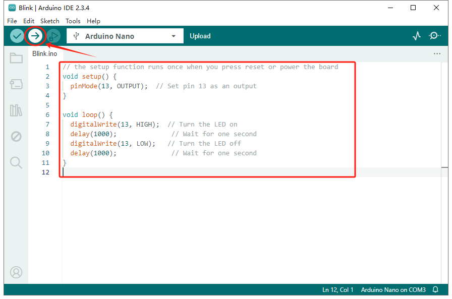
- Once the upload is complete, the Onboard LED (connected to pin 13) on the Arduino Nano should begin blinking, indicating that the program has been successfully uploaded.
Conclusion
The Arduino Nano is a versatile and compact board ideal for a variety of electronics projects. Whether you’re working on a small embedded system or an IoT device, the Nano’s small size, combined with powerful features like digital I/O pins, analog inputs, and support for various communication protocols, makes it a valuable tool for both beginners and experienced makers alike. The multiple variations of the Arduino Nano, including models with Wi-Fi, Bluetooth, and additional sensors, provide even more flexibility for a wide range of applications.

