Fork-style spade connectors are useful when a PCB assembly needs a serviceable wire-to-screw connection, but they are a poor default when vibration, hidden fasteners, or repeated field handling can let the tongue slip out. The right choice depends less on the connector name and more on the stack-up around it: stud size, wire class, crimp quality, torque control, current rise, and whether a technician must remove the lead without disassembling half the product.
This guide looks at spade connectors from the electronics side rather than the generic hardware aisle. If you are wiring a control PCB, power-entry board, DIN-rail assembly, or repairable field unit, the goal is to decide when a fork terminal is acceptable, when a ring terminal is safer, and what inspection points keep the joint from becoming a nuisance failure.
What a spade connector actually solves in electronics work
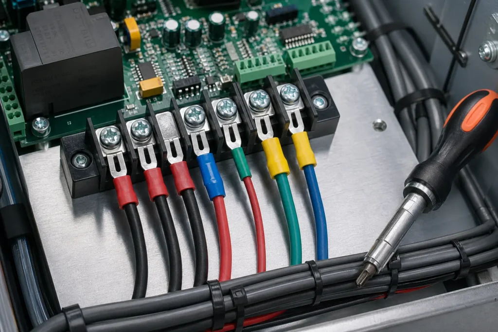
A spade connector gives you faster service access than a ring terminal because the screw usually needs only partial loosening before the wire can be removed. That matters on barrier strips, chassis-mounted power distribution points, low-voltage control wiring, and bench repairs where a technician may need to isolate one branch quickly. In electronics equipment, the value is service speed and reduced teardown time, not raw electrical superiority.
The tradeoff is mechanical security. Because the forked tongue is open, any loss of clamp force can let the terminal walk out sideways. On a quiet enclosure that stays on a wall, that risk may be acceptable. On a vibrating motor drive, mobile machine, compressor controller, or high-current heater board, the same geometry can create intermittent power drops, nuisance alarms, brownouts, or localized heating at the screw pad.
Where spade connectors fit on a PCB-related assembly
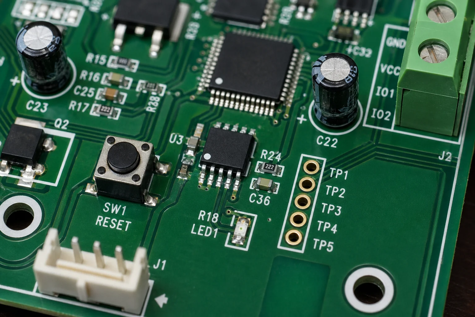
Spade connectors make the most sense when the PCB is only one part of a broader electromechanical assembly. Common examples include transformer secondary leads landing on a screw terminal block, harness wires from a panel switch returning to a control board, removable sensor wiring on a service panel, or low-voltage accessory outputs on industrial electronics. In those cases, the connector is part of the field wiring strategy, not part of the bare PCB itself.
They are much less attractive when the wire lands directly on a board-mounted screw terminal that sees vibration, repeated shipping shock, or frequent user access. If the board flexes, the screw loosens, or the harness pulls sideways, the spade tongue has little redundancy. A ring terminal or a pluggable terminal block usually buys more retention margin. If your design already struggles with wire routing, creepage spacing, or strain relief, a fork terminal rarely fixes the root problem.
When a ring terminal or another option is the better choice
Use a ring terminal instead when accidental disengagement would create a safety risk, an expensive field visit, or a hard-to-diagnose intermittent fault. Chassis grounds, mains-adjacent wiring, higher-current returns, compressor leads, fan power feeds, battery connections, and mobile equipment are all poor places to be optimistic about an open fork staying captured forever. A ring terminal forces full screw removal before service, but that inconvenience often buys better fault containment.
A ferrule is better when the wire lands in a clamp-style terminal rather than under a screw head. A quick-disconnect blade terminal is better when the mating tab is fixed and repeated plug/unplug service is expected. Direct soldering can still be appropriate for controlled internal wiring, but only when repair access, heat damage, and conductor fatigue have been considered. If your design is still deciding between fixed wiring and connectorized service access, USB wiring schematic checks that prevent miswired connectors on real boards is a useful reminder that the mechanical interface and the electrical interface have to be reviewed together. The mistake is treating all wire-end terminations as interchangeable because they fit the same current number on a catalog page.
Selection points that matter more than the catalog photo
Choose the connector from the mechanical stack first. The stud width must match the screw without leaving excessive side play, and the tongue width must fit the available keep-out area without overhanging adjacent metalwork. After that, match the conductor barrel to the real wire class and strand count, not just the nominal AWG on the drawing. Fine-strand hook-up wire can crimp very differently from stiffer appliance wire.
Plating, insulation sleeve material, and temperature rating also matter. Tin-plated copper or brass is common and usually adequate indoors, but humid cabinets, mildly corrosive vapors, or large thermal swings may justify better corrosion control and sealing strategy around the joint. If the assembly runs warm, the question is not only ampacity. It is whether the terminal barrel, screw, mating pad, and adjacent polymer parts can tolerate the local temperature rise without relaxation, discoloration, or loss of spring force.
Crimping and inspection checkpoints that prevent nuisance failures
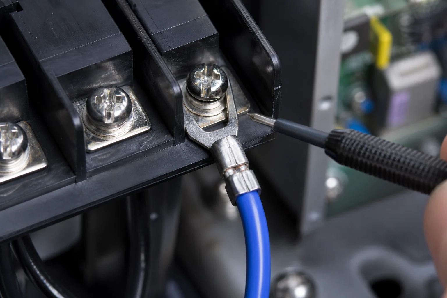
A spade connector is only as good as the crimp. The stripped length must let conductor strands fully enter the barrel without stray whiskers exiting the seam. The crimp die must match the terminal family, because a barrel crushed with the wrong profile can look acceptable while carrying less pull strength and higher contact resistance. Insulation support should grip the jacket without biting through it, especially on harnesses that will be tied down close to the termination.
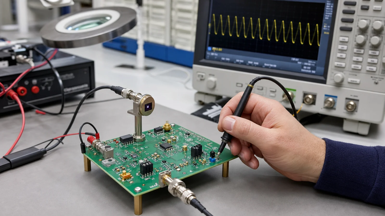
Inspection should include more than a glance. Check for full strand capture, proper bellmouth, centered conductor brush, absence of cracked insulation sleeves, and no visible twist that suggests the wire was inserted while loaded sideways. On prototypes and first articles, do a simple pull test and then torque the landed screw to the real assembly value. If current is significant, use an infrared check or loaded voltage-drop measurement after thermal soak. Many fork-terminal problems are not immediate opens; they begin as subtle heating and only fail after several power cycles.
Common failure modes on boards, panels, and field repairs
The most common field failure is gradual loosening followed by intermittent contact. Vibration, copper strand creep, soft insulation cold flow, or simple under-torque can reduce clamp force over time. The second common problem is wrong barrel sizing, where a terminal intended for a larger wire is crimped onto a smaller conductor and passes visual inspection while failing under pull or thermal load. The third is misapplication: using a spade terminal where the wire exits sideways and constantly pries against the screw.
Repair work adds another risk. Once a connector has been overheated, tarnished, or re-crimped after a field splice, it may no longer deserve trust in a permanent repair. If the conductor strands have broken, the insulation has receded, or the terminal tongue has been bent open during removal, replacement is usually faster than defending a marginal joint. This is especially true near power supplies, relays, heaters, and motors where intermittent contact can propagate into broader board damage. When a repair calls for abandoning the screw-landed approach altogether, soldering wires directly to a circuit board may be the better controlled option, but only if strain relief and rework access are handled deliberately.
A practical rule for deciding whether to use one
Use a spade connector when you need faster service access on a screw-landed wire, the enclosure environment is controlled, the harness is strain-relieved, and loss of clamp force will be noticed before it becomes destructive. Do not use one just because it is easy to install. If the connection is critical, hidden, safety-related, high-current, or exposed to vibration, step back and ask whether a ring terminal, ferrule, pluggable terminal, or redesigned interconnect is the more honest engineering choice.
That decision discipline matters more than connector vocabulary. In electronics builds, the connector that looks convenient on the bench can become the callback that wastes the most time in the field.
FAQ
Are spade connectors reliable enough for PCB-related equipment?
They can be reliable on low-vibration, serviceable assemblies when the wire is properly crimped, strain-relieved, and torqued under a secure screw terminal. They are a weaker choice when the assembly sees vibration, hidden access, high current, or safety-critical grounding duties.
What is the main difference between a spade connector and a ring terminal?
A spade connector can usually be removed after partially loosening the screw, which speeds service. A ring terminal fully encircles the screw, so it is slower to remove but much harder to dislodge accidentally if clamp force drops.
Can I use a spade connector directly on a board-mounted screw terminal?
Yes, but only if the board, terminal, and harness geometry support it. Check board flex, wire pull direction, creepage clearance, torque retention, and whether field vibration could let the fork slip out under the screw head.
What should I inspect after crimping a spade connector?
Verify full strand insertion, correct die profile, insulation support, no broken strands, proper screw fit, and stable temperature or voltage drop under load. For prototypes or critical circuits, add a pull test and a torque-confirmed assembly check.