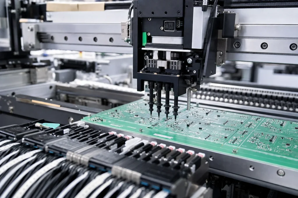
The SMT pick-and-place process is easy to oversimplify because the machine movement is the most visible part. Boards move in, nozzles move fast, and components land where the program tells them to go. That visual speed makes it tempting to think placement quality is mainly about machine capability. In practice, the process depends just as much on feeder setup, centroid data, package orientation, nozzle fit, panel support, and how the upstream print step prepared the job.
When engineers search for an “SMT PNP process,” they are usually trying to understand how parts are picked from reels, trays, or tubes and placed onto solder paste accurately enough for reflow to finish the joint. The useful answer is not just that the machine picks and places parts. It is how the full placement process loses accuracy, throughput, and yield when the data and mechanics behind that motion are weak.
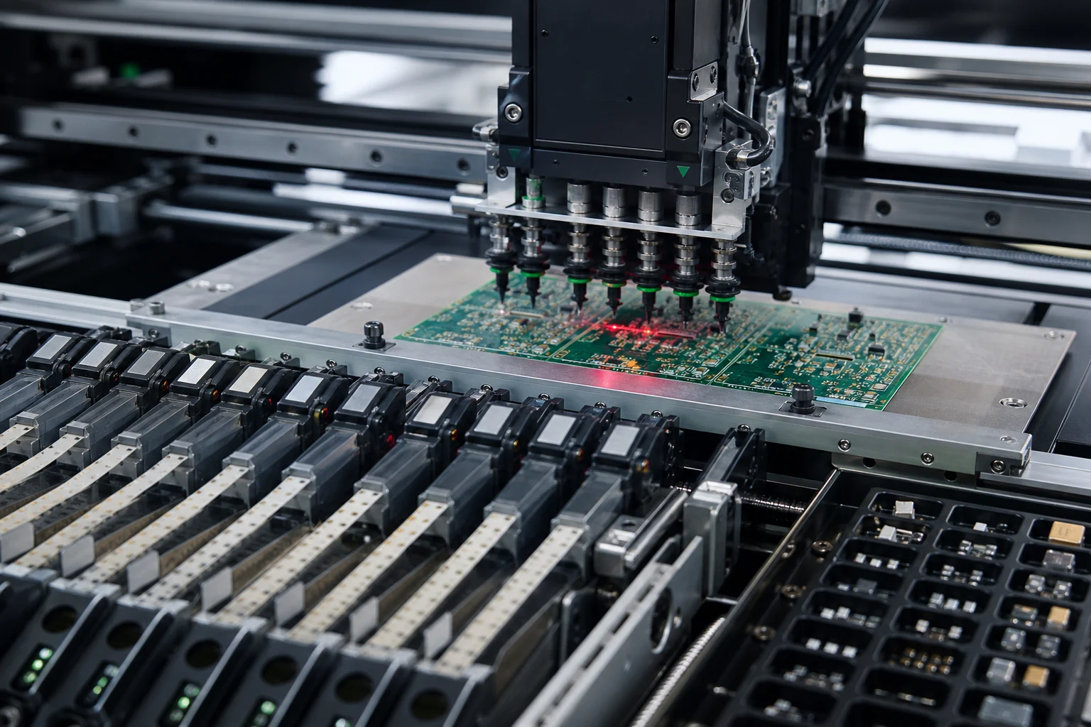
What happens during the SMT pick-and-place process
After solder paste printing, the board or panel enters the placement stage. The machine identifies the product recipe, references fiducials, pulls components from feeders or trays, checks orientation and presence through its vision system, and places each part onto the pasted pads. That summary sounds linear, but every step is tied to data quality and mechanical stability. A board can have a fast placement cycle and still build poor joints if paste volume, centroid coordinates, or support conditions are wrong.
The placement stage also does not stand alone. ReversePCB’s guide to SMT stencil and print quality control matters here because the placement machine is trying to land a component onto a real paste deposit, not onto a perfect CAD drawing. If the print is inconsistent, the pick-and-place stage inherits that instability even when placement repeatability is good.
The data the machine needs before placement is reliable
The most important invisible input is component data. Footprint library origin, centroid coordinates, rotation convention, package height, pickup point, and feeder assignment all affect placement quality. A placement machine can be extremely accurate and still place a part badly if the library origin is wrong or the rotation rule does not match the package orientation on the reel.
That is why first article builds often fail quietly before anyone blames the line. The program may run, the machine may not alarm, and yet one polarized part is rotated, one odd-form component is mis-centered, or one tray-fed IC is picked from a slightly wrong pocket geometry. The process problem lives in the release data, not in servo precision alone.
Where the SMT PNP process usually breaks down
Feeder and packaging mismatch
A reel component with poor cover tape behavior, wrong pitch setup, or inconsistent pocket release can create intermittent pickup loss that looks random until the feeder station is reviewed. Tray parts and stick-fed parts add their own constraints, especially when package body shape makes vacuum pickup less forgiving.
Vision and polarity errors
Vision systems help, but they only confirm what the camera and algorithm are configured to read. Weak polarity marks, reflective bodies, unusual leadframes, and custom packages can produce borderline inspections that pass on some cycles and fail on others. Engineers need to treat orientation validation as part of process engineering, not as an automatic guarantee.
Board support and placement force
Thin boards, large panels, and local unsupported areas can flex under placement force. On dense products, that small movement is enough to reduce consistency on fine-pitch parts or bottom-terminated packages. The placement program may still be “on target” in machine coordinates while the board itself is not behaving rigidly enough underneath.
Why speed is not the first placement metric to optimize
High placement rate looks impressive, but placement quality is more valuable than theoretical components per hour if the build then loses yield at reflow or AOI. A line running too aggressively for the feeder mix, nozzle maintenance condition, or board support setup may create more head-in-pillow risk, skew, and misalignment than its throughput gain is worth.
This is why ReversePCB’s article on what belongs in an SMT assembly line focuses on system balance rather than machine headline numbers. The placement stage has to match paste stability, inspection coverage, board complexity, and reflow capacity. A fast PNP process inside an unbalanced line only moves defects downstream more efficiently.
Checks worth doing before first article approval
A practical first article review should verify more than whether parts are present.
Confirm library origin and rotation on the risky packages
QFNs, odd-form connectors, LEDs, electrolytics, diodes, and asymmetric passives deserve focused review because these are the parts most likely to expose data and orientation mistakes early.
Check nozzle choice and pickup stability
Nozzle size, vacuum behavior, and component body support should match the package family being placed. Pickup loss that appears occasional in setup often becomes expensive in volume.
Check board support around dense or fragile zones
Large BGAs, fine-pitch controllers, shielded areas, and thin local board sections should be reviewed for panel support so the machine is not placing onto a flexing surface.
How the placement stage connects to downstream quality
Placement quality influences far more than whether a component looks centered before reflow. It affects solder-joint geometry, bridging margin, tombstoning tendency, optical inspection reliability, and later rework difficulty. That is why the SMT PNP process belongs inside a broader SMT assembly process control discussion rather than as an isolated machine topic.
The best placement teams treat every placement error as a traceable system problem: data, feeder, vision, board support, component packaging, or upstream paste quality. That mindset fixes recurring defects faster than simply slowing the machine and hoping stability improves.
Conclusion
The SMT pick-and-place process is the discipline of turning CAD data, packaged components, and printed boards into accurate placement that reflow can finish reliably. Machine speed matters, but dependable placement comes from correct centroid data, feeder control, vision confidence, panel support, and a strong connection to the rest of the SMT line. When those inputs are controlled, the process scales. When they drift, the machine only places mistakes faster.
FAQ
What is the SMT pick-and-place process?
The SMT pick-and-place process is the assembly stage where machines pick components from reels, trays, or tubes and place them onto solder-pasted PCB pads using programmed coordinates, vision checks, and feeder control.
What causes placement errors in an SMT PNP process?
Common causes include wrong centroid data, rotation mistakes, feeder pitch problems, weak polarity recognition, poor board support, nozzle mismatch, and unstable solder paste deposits from the upstream print stage.
Why is feeder setup important in pick-and-place?
Feeder setup controls how consistently the machine can present each component for pickup. If the pitch, pocket release, or reel handling is unstable, the machine may miss pickups or place parts inconsistently even with a good program.
Does faster pick-and-place always improve SMT output?
No. Higher speed only helps when data, feeders, board support, and upstream print quality are already stable. Otherwise the line may gain nominal throughput while losing yield and inspection stability.