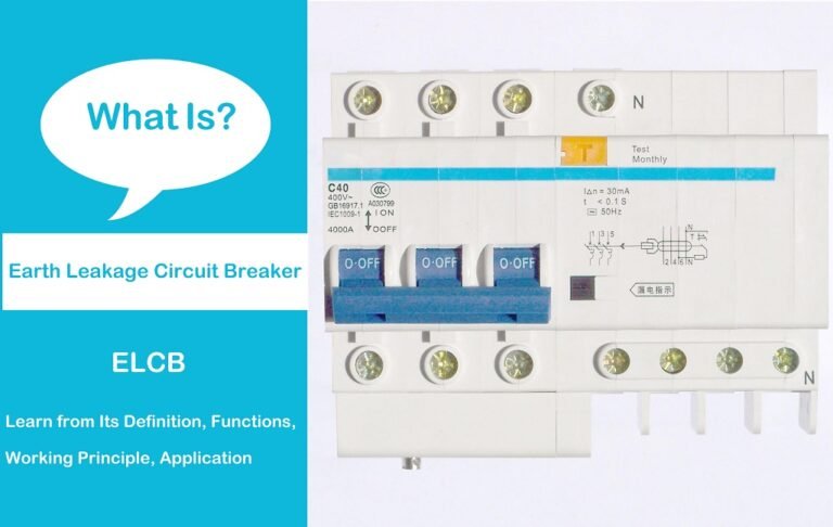
What is an Earth Leakage Circuit Breaker?
An earth leakage circuit breaker (ELCB), also known as an earth leakage switch or earth leakage protector, is an electrical safety device. It is mainly used to automatically disconnect the power supply to protect the human body from electric shock when a leakage fault occurs in the equipment.
Some leakage circuit breakers on the market only have the function of leakage protection and power-off, and must cooperate with protective elements such as fuses, thermal relays, and over-current relays when used. Of course, some leakage circuit breakers also have protection functions such as leakage, electric shock, overload, and short circuit.
The Structure of ELCB
Leakage circuit breaker is actually a superposition of ordinary circuit breaker and leakage protection module, the details are as follows:
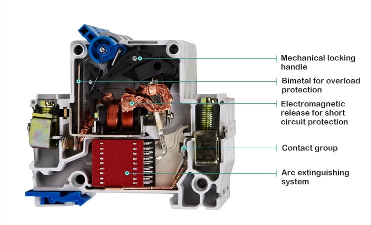
Circuit Breaker
The circuit breaker is mainly composed of contacts, arc extinguishing system, electromagnetic release, transmission mechanism, and insulating shell, etc., and plays the functions of on-off, control, and protection in the circuit.
Leakage Protection Module
Leakage protection module is mainly composed of measurement components, calculation and amplification components, operation execution components, test components and so on.
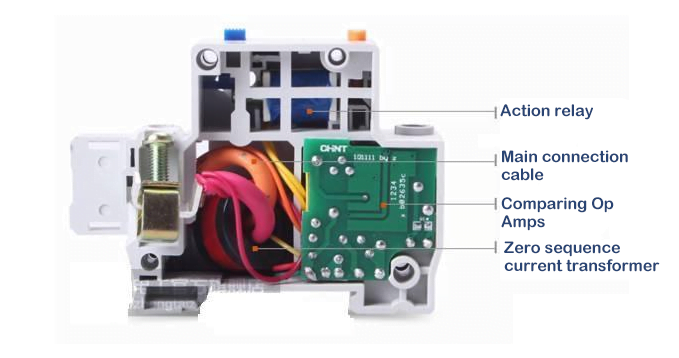
- The measuring element is mainly composed of zero-sequence transformers, which can detect leakage current and send out signals.
- The operational amplifier component is a complete set of circuit devices composed of rectifier bridge, thyristor, resistor and capacitor, etc., which can amplify the weak leakage current and conduct it to the actuator.
- The actuator is composed of relays and other parts, which can drive the main switch for protective tripping after receiving the signal.
- The test element is a set of independent circuits composed of test buttons and resistors, which can skillfully simulate the leakage state to test whether the function of the protector is normal.
How does ELCB Work?
As shown in the figure below, it is the working principle diagram of ELCB.
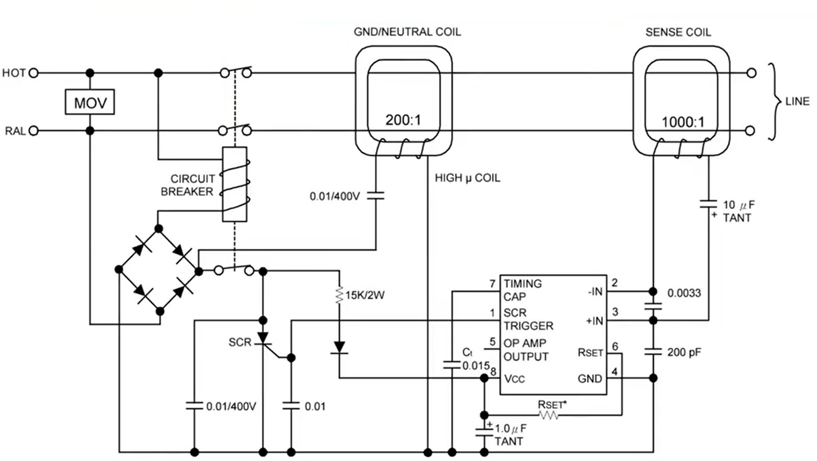
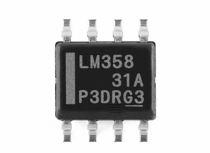
The pins of the circuit chip are described as follows:
- pin 1 is the SCR trigger pin
- pin 2 is the inverting input terminal of the operational amplifier inside the chip
- pin 3 is the non-inverting input terminal of the operational amplifier inside the chip
- pin 4 is the ground pin
- pin 5 is the output terminal of the operational amplifier inside the chip
- pin 6 is the current sampling
- pin 7 is the delay capacitor
When the equipment is operating normally, the currents of the live wire and the neutral wire are equal, and the current transformer has no induction current at this time. The sum of the current vectors in the transformer is zero (the current is a directional vector, such as “+” in the direction of outflow, and “-” in the return direction. offset).
When a leakage occurs and the current is greater than 30mA, the current transformer generates an induced current, making the voltage at pin 2 of the chip greater than that at pin 3, and pin 1 of the chip outputs a high level. The thyristor is triggered and turned on after obtaining a high level, and the tripping coil is energized to trip. This is the working principle of earth leakage circuit breaker.
Types of ELCB
According to working principle, there are three main types of ELCBs:
Voltage-Operated ELCB (VO-ELCB)
This type of ELCB operates based on the voltage difference between the line and neutral conductors. When a fault occurs, causing a leakage current, the voltage difference triggers the ELCB to trip and disconnect the circuit. VO-ELCBs are commonly used in residential and small commercial applications.
Current-Operated ELCB (CO-ELCB)
CO-ELCBs work by monitoring the imbalance in current between the live and neutral conductors. When a fault occurs, causing a leakage current, the imbalance triggers the ELCB to trip and disconnect the circuit. CO-ELCBs are typically used in larger commercial and industrial applications.
Residual Current Circuit Breaker (RCCB)
RCCBs are an advanced type of ELCB that can detect both AC and DC leakage currents. They use a sensitive current transformer to monitor the difference in current between the outgoing and returning conductors. If a leakage current is detected, the RCCB will trip and interrupt the circuit.
According to the number of circuit breakers, ELCB can also be divided into 1P+N, 2P, 3P, 3P+N, 4P types.
1P+N Type
This type is composed of a single (1P) ordinary circuit breaker and a leakage protection module, and has two sets of terminals. The biggest feature of the device is that only one pole has thermal magnetic tripping breaking capacity, and the other pole does not have and is always in the conduction state. Therefore, when wiring the 1P+N type leakage circuit breaker, the live wire must be connected to the pole that can be broken, only in this way can safety be guaranteed.
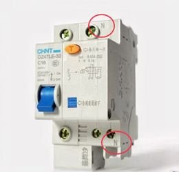
In order to prevent wiring errors, the manufacturer specially marked the terminals. As shown in the figure, the terminal marked N must be connected to the neutral wire, and the unmarked terminal must be connected to the live wire.
2P Type
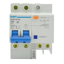
This type of leakage circuit breaker is the most widely used. It is a combination of a double (2P) circuit breaker and a leakage protection module, and has two sets of terminals. Both poles of this device have thermal-magnetic tripping and breaking capabilities, so there is no strict distinction between the wiring positions of the live wire and the neutral wire. Generally, it can be installed according to the custom and the site environment.
3P Type
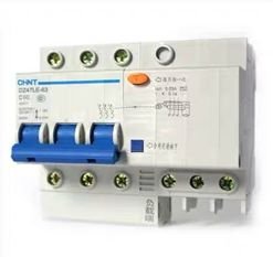
This type of leakage circuit breaker is composed of a triple (3P) circuit breaker and a leakage protection module. It is used in a three-phase balanced circuit. It has 3 sets of terminals, and all three poles can be turned on and off and have thermal magnetic tripping capability. When wiring, follow the sequence of phase wires A, B, and C to connect in sequence.
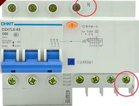
3P+N type
This type of leakage circuit breaker is composed of a triple (3P) circuit breaker and a leakage protection module. It is used in a three-phase unbalanced circuit and has 4 sets of terminals. Similar to 1P+N, one of the poles is always on and has no thermal-magnetic tripping breaking capacity, and the manufacturer has marked N (neutral line). The other three poles are connected in sequence according to the phase line sequence A, B, and C.
4P type
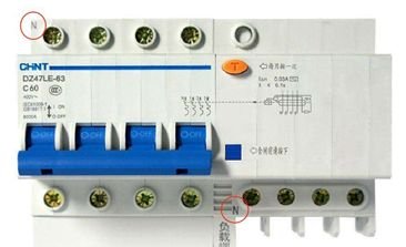
This type of leakage circuit breaker is composed of a quadruple (4P) circuit breaker and a leakage protection module. It is applied in a three-phase unbalanced circuit. buckle ability. Due to the manufacturing process, the manufacturer has made fixed requirements on the access position of the neutral line N, as shown in the figure. For the phase lines A, B, and C, they are connected to the other three groups of terminals in sequence.
Common faults of ELCB
01: Contacts Can't be Closed under Manually Operated
Cause Analysis:
- The voltage-loss release has no voltage or the coil is burnt out;
- The energy storage spring is deformed, resulting in a decrease in the closing force;
- The reaction spring force is too large;
- The mechanism cannot reset and trip;
- The transmission mechanism is not flexible.
Solution:
- Check the circuit, apply voltage or replace the coil;
- Replace the energy storage spring;
- Readjust;
- Adjust the tripping contact surface to the specified value;
- Add a little engine oil to the transmission point.
02: Contacts Can't be Closed under Electrically Operated
Cause Analysis:
- The operating power supply voltage does not match;
- The power capacity is not enough;
- The stroke of the electromagnet rod is not enough or the gap between the armature is too large;
- Motor operation positioning switch failure;
- The rectifier tube or capacitor in the controller is damaged.
Solution:
- 1. Replace the power supply;
- Increase the operating power capacity;
- Readjust or replace the tie rod or raise the iron core;
- Readjust the operation positioning;
- Replace the rectifier tube or capacitor.
03: One Phase Contact Can't be Closed
Cause Analysis:
- A connecting rod of the circuit breaker is broken;
- The angle of the transmission mechanism of the current limiting element is not suitable.
Solution:
- Replace the connecting rod;
- Adjust to the requirements of the original technical conditions.
04: The Shunt Release Can't Disconnect the Circuit Breaker
Cause Analysis:
- Coil short circuit;
- The power supply voltage is too low;
- The tripping contact surface is too large;
- The screws are loose.
Solution:
- Replace the coil;
- Replace or increase the power supply voltage;
- Readjust the tripping contact surface;
- Tighten the screws.
05: Loss of Voltage Release Can't Break the Circuit Breaker
Cause Analysis:
- The reaction force spring becomes smaller;
- The energy storage spring becomes smaller;
- The mechanism is stuck.
Solution:
- Adjust the spring;
- Adjust the energy storage spring;
- Eliminate the cause of stuck.
06: The Circuit Breaker is Disconnected when Lauching the Motor
Cause Analysis:
- The instantaneous setting current of the overcurrent release is too small;
- Phase failure protection or other protection actions.
Solution:
- Adjust the instantaneous setting spring of the overcurrent release and other protections;
- If it is an air release, the valve may fail or the rubber membrane may be broken.
07: The Circuit Breaker Open Automatically after Closed
Cause Analysis:
- The long delay setting value of the overcurrent release is wrong;
- Deterioration of heating element or semiconductor delay circuit element.
Solution:
- Readjust the overcurrent release;
- Replace damaged components.
08: Loss of Voltage Release Produces Noise
Cause Analysis:
- The reaction force spring is too strong;
- There is oil on the working surface of the iron core;
- The short circuit ring is broken.
Solution:
- Readjust the reaction spring;
- Eliminate oil pollution;
- Replace the armature or core.
09: Circuit Breaker Overheating
Cause Analysis:
- The contact pressure is too low;
- Excessive wear or poor contact on the contact surface;
- The connecting screws of the two conductive parts are loose.
Solution:
- Adjust the contact pressure or replace the spring;
- Replace the contacts or clean the contact surface;
- Tighten the screws.
10: Auxiliary Switch Failure
Cause Analysis:
- The movable contact bridge of the auxiliary switch is stuck or falls off;
- The drive rod of the auxiliary switch is broken or the roller falls off.
Solution:
- Correct or reinstall the contact bridge;
- Replace the transmission rod and roller, or replace the entire auxiliary switch.
Pros and Cons of ELCB
Pros:
- Enhanced safety
- Quick response time
- Easy installation
- Cost-effective
Cons:
- Sensitivity limitations
- Potential nuisance tripping
- Limited protection range
- Maintenance requirements
Applications of ELCB
- Residential buildings, such as bathrooms, kitchens, and electric water heaters
- Entertainment place, such as swimming pools, spas, and outdoor recreational facilities
- Household appliances, such as air conditioning units, refrigerators, washing machines
- Industrial fields, such as manufacturing plants, workshops, and construction sites

