What is MMBT3904?
MMBT3904 is a type of NPN transistor, which is a type of electronic component used to amplify or switch electronic signals. It is commonly used in amplifiers, voltage regulators, and motor control circuits.
Features of MMBT3904
- Collector DC current: 200mA
- HFE:300
- Number of pins: 3
- SMD mark: 1A
- Power Consumption: 350mW
- Device marking: BT3904
- Maximum noise factor (NF): 5dB
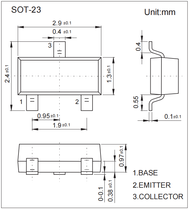
- Package Type: SOT-23
- Transistor count: 1
- Transistor Type: General Purpose Small Signal
- Maximum continuous current: 200mA
- Minimum Gain Bandwidth: 300MHz
- Voltage: 60V
- Current: 10mA
- Maximum current (Ic): 200mA
- DC current gain hfe, min: 100
- Surface Mount Devices: Surface Mount
- Maximum voltage: 0.2V
Pin Configuration

Pin 1: Emitter, current flows out through the emitter, usually grounded.
Pin 2: Base Controls the bias of the transistor, used to turn the transistor on or off.
Pin 3: Collector Current flows in through the collector, usually connected to the load.
How does MMBT3904 Transistor Work?
The collector and emitter will remain open (reverse biased) when the base is grounded and closed (forward biased) when a signal is supplied to the base pin.
In order to bias the transistor we have to supply a current (Ib) to the base pin, this current should be limited to 5mA, when this transistor is fully biased, it can allow a maximum of 200mA to flow through the collector and emitter, this stage Known as the saturation region, the typical voltages allowed across the collector-emitter (Vce) or collector-base (Vcb) are 40V and 60V, respectively.
When the base current is removed, the transistor is completely turned off, this phase is called cut-off region. The emitter-base (Veb) voltage can be around 6V.
Package
MMBT3904 Typical Circuit Schematic
The following is a typical circuit schematic for MMBT3904:

The diagram shows a lighting circuit design with 3 LEDs connected in parallel and in series, ensuring that all LEDs are equally bright (as they have roughly the same forward voltage) and provide full brightness source voltage above 7V when powered.
When VIN is low, the LEDs are connected in parallel, and vice versa, they are connected in series. Additionally, the schematic only requires a 4V voltage to output light, making it ideal for low-voltage applications. Furthermore, this schematic is suitable for applications that require low harmonic distortion and are consistent with TRIAC dimmers.
Transistors Q1-Q4 are closed, while the other transistors are open, and S1 (Schottky diode BAT54) is cut off, causing the circuit to work in parallel. On the other hand, when Q5, Q6, Q9, and Q10 are closed and S1 is conductive, the circuit works in series.
MMBT3904 Pinout and Substitution Checks
The MMBT3904 is commonly supplied in SOT-23, but a top mark or family name is not enough to approve placement. Verify the exact manufacturer drawing, reel orientation, and MMBT3904 datasheet limits before assembly or substitution.
- Confirm the pinout: a common SOT-23 drawing assigns pin 1 to base, pin 2 to emitter, and pin 3 to collector; release the footprint only against the selected supplier’s drawing.
- Check an unknown part: in diode mode, the positive probe on the base should forward-bias both base-emitter and base-collector junctions, while collector-emitter remains open at low test voltage.
- Derate the ratings: typical family limits such as
VCEO = 40 VandIC = 200 mAare absolute maxima; verify safe operating area and package power at the real PCB temperature. - Match circuit behavior: compare minimum
hFEat the specified current,VCE(sat)at the stated forced beta, transition frequency, capacitances, leakage, and switching time. - Validate the build: check footprint, top-mark traceability, tape orientation, temperature grade, and qualification, then use current-limited power to verify collector polarity, base drive, load current, and heating.
Applications of MMBT3904
- Driver modules, such as LED drivers, relay drivers;
- Amplifier modules such as signal amplifiers, audio amplifiers;
- Both Vcb and Vce are high so can be used to control voltage loads up to 40V;
- Ideal for portable devices;
- Small Load Switching Transistor with High Gain and Low Saturation Voltage;
- Commonly used in home appliances such as TVs.