Circuit Parameters
Calculated Results
Frequency Response
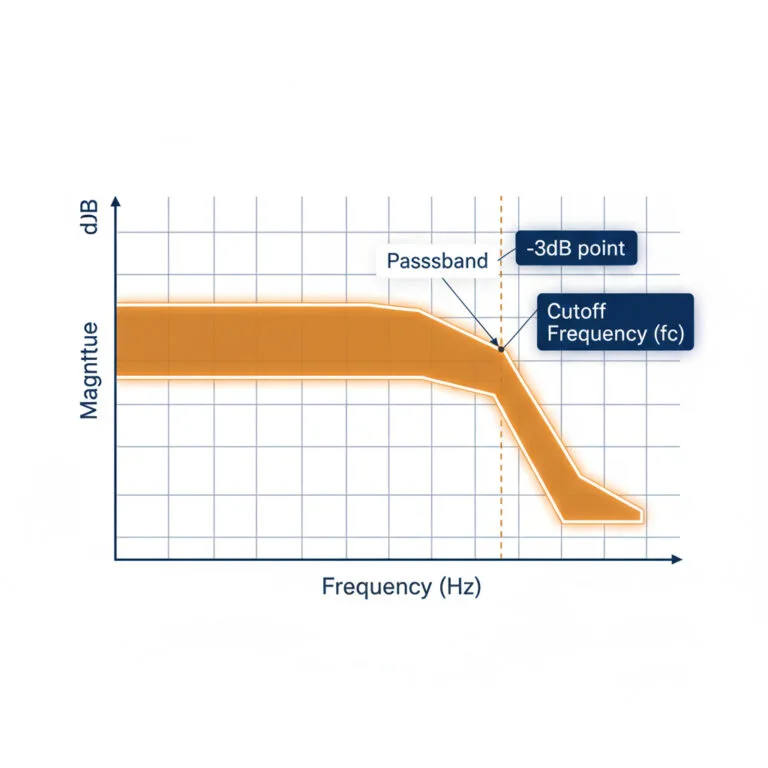
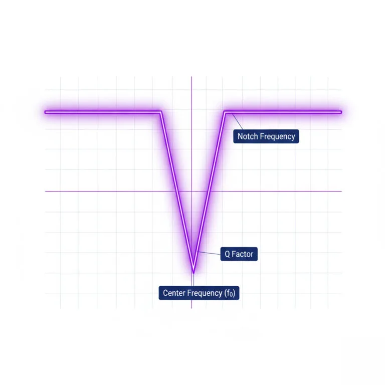
This chart shows the circuit's impedance across a range of frequencies. Notice the sharp dip at the resonant frequency for the series circuit.
What is Resonance?
In an RLC circuit, resonance is a condition that occurs at a specific frequency, called the resonant frequency (f0). At this frequency, the inductive reactance (XL) and capacitive reactance (XC) are equal in magnitude and cancel each other out. This causes the circuit to behave as if it's purely resistive. The result is a dramatic change in the circuit's total impedance (its opposition to current flow), leading to a peak in current (for series circuits) or voltage (for parallel circuits). This phenomenon is fundamental to tuning circuits used in radios, filters, and oscillators.
Comparison of RLC Circuits
Series RLC Circuit
- At Resonance: Impedance is at its minimum (Z = R).
- Current: Maximum at resonance.
- Primary Use: Band-pass filters, allowing signals near f0 to pass.
Parallel RLC Circuit
- At Resonance: Impedance is at its maximum (theoretically infinite, practically R).
- Current: Minimum at resonance.
- Primary Use: Band-stop (notch) filters, blocking signals near f0.
Key Formulas
Resonant Frequency (f0)
The fundamental frequency where reactances cancel. f₀ = 1 / (2π * √(LC))
Angular Frequency (ω0)
Frequency in radians per second. ω₀ = 1 / √(LC)
Quality Factor (Q) - Series
Indicates the sharpness of the resonance peak. Q = (1/R) * √(L/C)
Quality Factor (Q) - Parallel
Indicates the sharpness of the resonance peak. Q = R * √(C/L)
Bandwidth (BW)
The range of frequencies where power is at least half the maximum. BW = f₀ / Q
Impedance (Z)
Total opposition to current, varies with frequency. See chart.