Identify the Device and Instrument Configuration
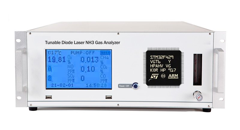
The STM32F429VGT6 is an Arm Cortex-M4 microcontroller with a floating-point unit, a maximum CPU frequency of 180 MHz and 1 MB of embedded Flash in an LQFP100 package. ST lists 256 KB of SRAM, including 64 KB of core-coupled memory (CCM). These memory banks have different access characteristics; CCM is not a general-purpose DMA buffer.
Confirm the complete device marking, board revision, sensor type, firmware version and external memories before planning maintenance. ST’s STM32F427xx/STM32F429xx datasheet provides the device and package definitions. A microcontroller’s capabilities do not establish the architecture or measurement performance of an instrument built around it.
Lead image: equipment-and-MCU illustration for context.
Map Supported Debug and Board Connections
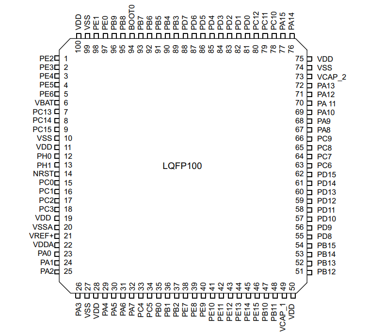
The SWD signals are PA13/SWDIO and PA14/SWCLK. For the LQFP100 package, these are pins 72 and 76; NRST is pin 14. Confirm package orientation and trace the actual board nets before connecting a supported probe. Include the target supply reference, ground, reset arrangement and any components shared with the debug lines in the connection record.
A wired debug connector does not establish that protected memory is readable. Record the device identity and access state reported by the manufacturer’s tools, then check the applicable documentation before any erase, programming or option-byte operation. Separate a connection problem, a boot problem and a readout-protection restriction rather than treating all three as an encrypted-chip failure.
Distinguish Readout Protection from Encryption
The STM32F429 readout-protection levels control access to memory and debug functions. They do not automatically encrypt the application or make normal user-code execution impossible. Diagnose the instrument’s reported fault separately from the MCU’s protection state.
ST’s RM0090 reference manual describes the protection levels and their consequences. Returning from Level 1 to Level 0 triggers a mass erase of main Flash and backup SRAM. Level 2 is irreversible: it cannot be downgraded through the supported programming interface. An erase or protection-regression operation is incompatible with preserving an existing Flash image.
The STM32F429 does not provide the dedicated cryptographic processor found in the STM32F439 variant. An application can still implement encryption in software or use an external component. Establish that from application-specific evidence; neither an unsuccessful read nor a fixed word found in SRAM identifies an AES key or proves an encryption scheme.
Inventory Firmware, Calibration and Configuration Data
In the default single-bank organization, the VGT6 device’s 1 MB embedded Flash spans 0x08000000–0x080FFFFF. Check the configured bank organization and its documented address map before interpreting a memory image. Record file origins, address ranges and lengths for any approved firmware or backup. A raw binary needs a load address. Do not assume that a program image contains every item required to restore an instrument.
Calibration coefficients, sensor-specific constants, compensation tables, gas selections, alarm thresholds and service history may be stored in internal Flash, external memory or a separate configuration package. Identify their actual locations and versions from design records or reproducible analysis. Preserve the association between unit identity, sensor identity, firmware and calibration data; a file copied from another unit is not evidence of a valid calibration for this one.
Establish a Non-Destructive Assessment Baseline
Work only on equipment you own or are expressly authorized to service. Use an isolated service setup under the instrument manufacturer’s procedure, with the analyzer removed from any live process or protective duty. Record power conditions, boot behavior, fault indications, communication traffic and the documented access state before making changes.
If original contents must be retained, stop at an erase, unprotect or option-byte prompt. Seek approved update packages, source code, production binaries and calibration backups through the owner or manufacturer. Keep original captures and file hashes. Matching hashes show copy consistency; they do not by themselves establish firmware authenticity, complete recovery or correct measurement behavior.
Validate the Complete Instrument After Approved Maintenance
Firmware access and instrument acceptance are separate questions. An approved maintenance plan should specify the applicable firmware and configuration versions, calibration requirements and acceptance criteria before a change is made. Changes involving measurement or protective functions require the responsible instrument specialist’s review.
Use the manufacturer’s prescribed reference checks and procedures to assess zero and span behavior, response, fault reporting, logging, alarms and fail-safe states where applicable. Record the reference conditions, equipment, results and acceptance decision. Do not bypass interlocks or suppress alarms to obtain a passing result. This article does not replace model-specific service instructions or establish that a repaired instrument is fit for protective or medical use.
State the Evidence and Remaining Limits
A useful assessment report distinguishes manufacturer specifications, observed board behavior and conclusions inferred from analysis. Include tool versions, wiring, protection state, original files and the tests that support each conclusion. List remaining gaps such as unavailable calibration records, unknown external-memory formats or untested operating conditions.
This guide is a documentation-based maintenance framework. It reports no completed decryption campaign, recovery percentage, turnaround time or customer financial outcome. Any future project result needs its own records and validation evidence. Where protected original firmware is unavailable, describe the supported maintenance options and their limitations rather than promising extraction or full instrument recovery.
Discuss an authorized firmware and instrument assessment:

Principal Engineer:
Dr. Billy Zheng
Well Done PCB Technology
billy@reversepcb.com
Emergency Support: +86-157-9847-6858