Hey there, I’m Aidan, today we’ll introduce the ground in circuit. Early in my journey, I struggled with a simple question: “What is ground, really?” I’d see the symbol everywhere—circuits, tutorials, even in my Arduino projects—but it took years to grasp its depth. Let me share what I’ve learned, blending theory with hands-on experience.
What is Ground in a Circuit?
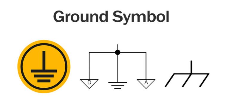
My confusion started with schematics. Why did some diagrams connect components to a zigzag symbol labeled “GND” instead of the battery’s negative terminal? Turns out, ground is just a reference point. In a single-battery circuit, it’s easy: ground = negative terminal.
But as circuits grow, ground becomes a shared “zero-volt” anchor for all components. And in many cases, it’s connected to the Earth or a large conductive object like a metal chassis. This connection is crucial for safety, acting as a safeguard against electrical shock.

Key Purposes of Grounding
Ground isn’t just a wire—it’s the unsung hero keeping your circuits safe, stable, and noise-free. Imagine a city’s sewage system: without it, waste (in this case, stray voltage and electrical noise) would overflow, causing chaos. Ground acts as your circuit’s “sewage system,” directing dangerous fault currents away from users and sensitive components while providing a stable 0V reference for signal measurements. A single bad ground can turn your amplifier into a hum machine, fry your PCB, or even electrocute someone.
Key Points
- Safety:
- Prevents electric shock by directing fault currents to the Earth, reducing the risk of injury to humans and animals.
- Triggers circuit breakers or fuses during faults, isolating the problem.
- Voltage Stability:
- Stabilizes voltage levels during transient events like lightning strikes or equipment malfunctions.
- Stabilizes voltage levels during transient events like lightning strikes or equipment malfunctions.
- EMI/RFI Reduction:
- Minimizes electromagnetic interference (EMI) and radio-frequency interference (RFI) by providing a path for noise to dissipate.
- Minimizes electromagnetic interference (EMI) and radio-frequency interference (RFI) by providing a path for noise to dissipate.
- Equipment Protection:
- Protects sensitive electronics from voltage surges and electrostatic discharge (ESD).
Different Types of Ground
Earth Ground

- Advantages: It’s a reliable safety measure. By providing a low – impedance path for fault currents, it protects people from electric shock and helps prevent electrical fires. In industrial settings, it’s a must – have for large machinery.
- Disadvantages: However, I discovered that in some sensitive electronic circuits, earth ground can introduce noise. This is because the Earth can act as a conductor for electromagnetic interference (EMI), which can mess with the signals in circuits like audio amplifiers.
- Applications: Earth ground is used in pretty much every household electrical appliance, from refrigerators to TVs, as well as in industrial electrical distribution systems.
Chassis Ground

- Advantages: Chassis ground makes wiring a lot simpler and can also help reduce electromagnetic interference by acting as a shield against external electromagnetic fields.
- Disadvantages: If not properly grounded, it can be a source of electrical shock. And as I experienced, it can introduce ground loops, which can cause all sorts of problems like noise in audio systems.
- Applications: It’s used in a wide range of automotive electronics, as well as in computers, where the metal casing often serves as a chassis ground.
Signal Ground
- Advantages: It helps reduce noise and interference in electrical signals, ensuring that the signals are clean and accurate. This is essential for things like audio amplifiers and radio receivers.
- Disadvantages: If not designed properly, it can actually introduce noise and interference. And it’s easily affected by ground loops, which can lead to signal distortion.
- Applications: Signal ground is used in all kinds of electronic circuits that deal with signals, from high – end audio equipment to communication devices.
Analog Ground and Digital Ground
- Advantages: Separating the two grounds reduces noise and interference between analog and digital signals, improving the performance and accuracy of the circuit.
- Disadvantages: It adds complexity to the circuit design. You need to be careful about how you connect the two grounds at a single point to avoid ground loops, and it may require additional components.
- Applications: This is used in mixed – signal integrated circuits, as well as in audio – video equipment and industrial control systems.
Virtual Ground
- Advantages: It allows for the creation of a stable reference point without a direct connection to the ground, which is useful in circuits that are sensitive to ground noise or where a physical connection to the ground isn’t possible.
- Disadvantages: It’s more complex to implement and requires careful design of the feedback loops. If the resistor values are off, the virtual ground won’t work as expected.
- Applications: Virtual ground is used in operational amplifiers, voltage regulators, and some audio amplifiers.
Ground Vs. Neutral and Bonding
As I gained more experience with electrical systems, I realized that there was often confusion between the terms “ground,” “neutral,” and “bonding.” While these terms are related, they have distinct meanings and functions.
Ground
Ground, as we’ve discussed, is a reference point in an electrical circuit that provides a common return path for current. It is often connected to the Earth or a large conductive object to protect against electrical shock.
Neutral
Neutral is a conductor that is used in alternating current (AC) electrical systems to provide a return path for current. In a typical AC circuit, the neutral wire is connected to the center tap of the transformer and is grounded at the service entrance. The neutral wire carries the unbalanced current in the circuit and helps to maintain a stable voltage.
Bonding
Grounding Troubleshooting and tips
Below are grounding mistakes I’ve made (and how to avoid them).
Troubleshooting Cases
The Case of the Floating Ground
Testing a circuit, I forgot to connect the ground wire. The multimeter showed random voltages, and the LED flickered. Lesson: Always connect ground. It’s the foundation, not an afterthought.
Ground Loop Horror Story
Recording vocals, my microphone picked up a 60Hz hum. The culprit? Two devices connected to different ground points, creating a loop. Fix: Use a DI box to break the loop and isolate the signal.
High-Frequency Nightmares
In a WiFi antenna project, my 2.4GHz signals kept degrading. I’d used long ground wires, which acted like inductors at high frequencies. Switching to a solid ground plane and short vias saved the day. Remember: High frequencies hate inductance.
Chassis Ground (My Car’s Secret Weapon)
When I installed a car stereo, I learned that the metal car frame acts as a chassis ground. Instead of running a separate wire for every component’s ground, I connected them all to the frame. It worked—until I added a subwoofer and heard a hum. Turns out, the alternator’s noise was sneaking into the ground loop. Moral: Chassis ground simplifies wiring but demands careful noise management.
Signal Ground: Why My Audio Setup Failed?
Building a guitar pedal, I mixed analog and digital components. The result? Distorted sound. I’d ignored signal ground separation—analog circuits need a quiet ground, while digital logic injects noise. Solution: Split the grounds and connect them at one point. Now my pedal sounds crisp!
Troubleshooting Tools
- Multimeter: Check continuity between grounds and Earth. A reading over 5Ω? Investigate.
- Oscilloscope: Spot noise on ground planes. A clean ground should be flat, not spiky.
- Clamp Meter: Test ground-fault currents in AC systems. If it’s over 5mA, something’s wrong.
Tips for PCB Design
- Layer Stacking: Dedicated ground planes reduce noise. For four-layer boards, route signals on top/bottom and sandwich ground/power in the middle.
- Decoupling Caps: Place 0.1μF caps as close as possible to ICs. Their ground legs should go straight to the plane.
- Star vs. Mesh Grounding: Star for low frequencies (one central point), mesh for high frequencies (grid of vias).
Grounding Standards and Regulations
- NEC (US): Requires grounding electrodes (e.g., driven rods) and bonding of metal enclosures.
- IEC (Europe): Emphasizes TN, TT, and IT system classifications.
- India (IS 3043): Specifies soil resistivity thresholds and electrode dimensions.
- Challenges: Global projects must reconcile conflicting standards (e.g., NEC’s 250.56 vs. IEC’s 62305 for lightning protection).
FAQ
Is ground the same as 0 volts?
In most cases, ground is considered the zero – volt reference. But I’ve learned that the actual voltage of ground can vary a bit depending on the circuit and the reference point. In some complex circuits, there might be a small voltage potential relative to other points in the circuit. So, while it’s generally seen as 0 volts, it’s not always that straightforward.
Is neutral the same as ground?
No, they’re not the same. Neutral is mainly for carrying the unbalanced current in an AC circuit, while ground is for safety and as a reference point. I remember being confused about this when I first started working with AC electrical systems, but once I understood their different functions, it made a lot more sense.
What happens if a circuit is not properly grounded?
I’ve seen firsthand the consequences of improper grounding. In a circuit I was working on, the lack of proper grounding caused the equipment to malfunction. There was also a risk of electrical shock. Without a proper ground connection, fault currents can’t flow safely, which can make electrical appliances dangerous to touch. It can also lead to electromagnetic interference, affecting the performance of electronic devices.
How do I test if a circuit is properly grounded?
I’ve used a few methods to test grounding. One is using a multimeter to measure the voltage between the ground terminal of the circuit and a known ground point, like a metal water pipe. If the voltage is close to zero, it’s a good sign. Another method is using a ground fault circuit interrupter (GFCI). It can quickly detect ground faults and cut off the power, protecting against electrical shock.