Advanced Options
Example Presets:
Received Power (\(P_r\)):
-25.0
dBmFriis Transmission Link Diagram
The Friis Transmission Formula
The Friis Transmission Equation is a fundamental principle in radio engineering that relates the power at a receiving antenna to the power delivered to a transmitting antenna. It assumes line-of-sight propagation in free space.
Linear Form
Logarithmic (dB) Form
This is the most common form used by engineers as it simplifies calculations by converting multiplication and division into simple addition and subtraction.
Variable Definitions
| Variable | Description | Common Units |
|---|---|---|
| \(P_r\) | Received Power | W, dBm, dBW |
| \(P_t\) | Transmit Power | W, dBm, dBW |
| \(G_t\) | Transmit Antenna Gain | dBi, dBd (unitless) |
| \(G_r\) | Receive Antenna Gain | dBi, dBd (unitless) |
| \(\lambda\) | Wavelength | m, cm |
| \(d\) | Distance between Antennas | m, km, miles |
Assumptions and Limitations
While the Friis equation is a powerful tool, it is an idealized model. For accurate real-world predictions, it is crucial to understand its core assumptions and limitations.
- Free Space: The formula assumes propagation in a vacuum, without any objects, reflections, or obstructions.
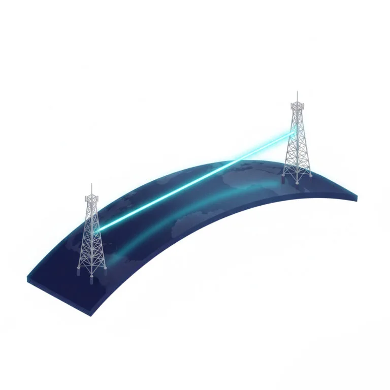
- Line-of-Sight (LOS): The antennas must be in a clear, unobstructed line of sight with no obstacles in the Fresnel zone.
- Far-Field: The formula is only valid when the antennas are far enough apart to be in each other's "far-field" region.
- No Losses: The basic formula does not account for real-world factors like cable losses, polarization mismatch, atmospheric absorption, or rain fade.
Practical Example: Wi-Fi Link
Let's calculate the expected received power for a typical home Wi-Fi link.
Scenario: A Wi-Fi router transmitting at 100 mW, with a 3 dBi antenna, to a laptop 20 meters away. The laptop has a 2 dBi antenna. The frequency is 2.4 GHz.
The calculator above can be used by setting \(P_t\) to 20 dBm (100 mW), \(G_t\) to 3 dBi, \(G_r\) to 2 dBi, distance to 20 meters, and frequency to 2.4 GHz.
Frequently Asked Questions
It's a mathematical formula used in telecommunications to calculate the power received by an antenna from another antenna in a free-space, line-of-sight environment.
You use the formula \(P_r = P_t + G_t + G_r - 20 \log_{10}(f) - 20 \log_{10}(d) - C\) (in dBm/dBi units) or the linear equation \(P_r = P_t \times G_t \times G_r \times \left(\frac{c}{4 \pi d f}\right)^2\). The calculator on this page automates this for you.
Yes, the calculator automatically converts inputs for Hertz (Hz), kilohertz (kHz), megahertz (MHz), and gigahertz (GHz) to the standard unit of Hertz for calculation.
Friis Calculator Inputs, Equation, and Free-Space Limits
A Friis calculator estimates received power between two antennas in unobstructed free space. In logarithmic units, the link is commonly evaluated as Pr = Pt + Gt + Gr - Lpath - Lsystem, with wavelength obtained from frequency. The Friis transmission equation assumes far-field operation, clear line of sight, correctly referenced antenna gains, and known system losses. It does not predict blockage, multipath fading, terrain, rain, polarization error, receiver sensitivity, or regulatory compliance by itself.
- Normalize every unit: convert power to dBm or dBW, gains to dBi, frequency to hertz, and distance to meters.
- Fix the reference planes: distinguish transmitter output, cable input, antenna terminals, and receiver input before adding gains or losses.
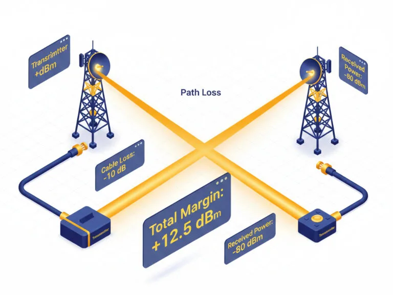
- Enter realistic losses: include feedlines, connectors, filters, polarization mismatch, pointing error, and any known atmospheric attenuation.
- Check model validity: confirm antenna far-field distance, Fresnel clearance, line of sight, and compatible polarization.
- Budget operating margin: compare calculated power with receiver threshold, then add fading, interference, implementation, and aging allowances.