Do you want to understand the intricate details of electrical termination in high speed signals? If so, you’ve come to the right place! This comprehensive guide will provide you with the tools you need to understand this complex subject. From the basics of termination, to the finer points of determining the correct termination impedances, this guide has you covered.
Whether you’re a student looking to learn more about high speed signal processing, an engineer working on a project, or just a curious individual, this guide will provide you with the necessary knowledge to make informed decisions about electrical termination in high speed signals. So, let’s jump right in and explore the world of electrical termination!
What is electrical termination?
Electrical termination refers to the process of terminating (ending) electrical cable with the proper termination impedance. The termination impedance is the ratio of voltage to current at the end of the transmission medium (where the cable meets the circuit board). The proper termination impedance is incredibly important to ensure safe, accurate transmission of data. If the termination impedance is incorrect, interference can occur, which can harm the cable, corrupt data, and even cause fires. Termination impedance is typically expressed as a value of resistance in ohms. This can be in direct connection (DC) or a high-frequency transformer (HF). For direct connection, often a resistor is used for impedance matching, whereas for a transformer, inductors are used. Termination impedance can also be expressed in terms of its S-parameter, which is a complex number that can be used to represent both the voltage and current characteristics of a transmission line.
Why is electrical termination important?
Electrical termination is important for multiple reasons. First and foremost, it is essential for safe and accurate data transfer. If the termination impedance is incorrect, this can lead to incorrect transmission and/or corruption of data. This can be especially problematic when dealing with high speed signals, as they are more susceptible to interference. Another reason termination is important is because it can affect transmission speed. If the termination impedance is incorrect or not properly matched, this can cause significant delays in data transmission. This is particularly true when dealing with high speed signals; any impedance mismatch can cause increased transmission delays. Last, but not least, termination is vital for power distribution. If the termination impedance is incorrect or not properly matched, this can cause an unbalanced load, which can lead to excessive power being drawn from the transmission lines. This can pose a major safety hazard, as it could even cause the transmission lines to catch fire.
Types of electrical termination
There are three general types of electrical termination: Series Termination, Parallel Termination, and Thevenin Termination.
Series Termination
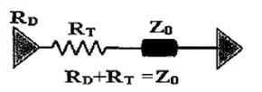
Series termination is the simplest form and most common method of termination. Its structure is shown in the figure below, a resistor R is connected in series between the end of the signal and the transmission line. This is typically used for very short lines, such as a few inches, with low-frequency signals. While the direct connection is simple and easy to implement, it is rarely used for high-speed signals as it does not offer any advantages over other termination methods.

Applications:
The general CMOS, TTL circuits, USB signals, and other low frequency signal circuits.
Parallel Termination
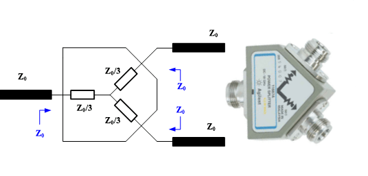
Parallel termination is a technology that eliminates reflections at the load end by adding parallel resistance to match the input impedance of the load end with the impedance of the transmission line. There are two common use parallel termination: single resistor and double resistor.

Applications:
DDR, DDR2 and other SSTL drivers, High-speed serial data interfaces such as TMDS.
Thevenin Termination
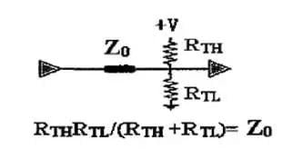
Thevenin termination is named after the French physicist ALéon Charles Thévenin and is a form of impedance matching. It is similar to parallel termination, with the only difference being that it has two resistors that are arranged in parallel.

Applications:
DDR2 address, control command signal circuits.
AC termination
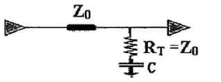
AC termination is actually adding a capacitor to the parallel termination. This termination method does not have any DC power consumption, and the AC power consumption is also very small.

Applications:
clock circuits.
Benefits of electrical termination
As discussed above, termination is important for many reasons. Among the most important reasons is that it provides accurate and clean signal transmission. This helps to ensure that the device receiving the signal is receiving the correct information. Additionally, termination provides increased safety by ensuring that the transmission line is receiving the correct amount of power. The line will receive an amount of power that is appropriate for the device connected to it. This minimizes the risk of the line being overpowered and causing a fire.
Calculating the correct termination impedances
To calculate the correct termination impedances, you must first know the type of transmission line you are using. There are many types of transmission lines, such as coaxial cables, twisted pair cables, and fiber optic cables. Once you know the type of transmission line, you can use manufacturer-provided data to determine the correct termination impedance. For example, let’s say that you are using a twisted pair cable to send data from one location to another. You will first need to know the impedance of the source. In the case of twisted pair cables, the source impedance is always 100 ohms. Next, you’ll need to know the characteristic impedance of the line, which is the impedance of the line when it is not loaded. The characteristic impedance of twisted pair cables is around 90 ohms. Finally, you need to know the distance of the line. The longer the line is, the lower the termination impedance will be. In the case of twisted pair cables, the termination impedance is typically expressed in terms of the number of ohms of capacitance required at the receiving end.
Commonly used termination techniques
There are many termination techniques, but many can be grouped into one of three categories: Termination with a Resistor, Termination with an Impedance Matching Network, and Termination with a Network Transformer.
Termination with a Resistor
This termination technique involves connecting a resistor between the transmission line and the ground. In the first method, the resistor is placed at the source end of the transmission line, and a matched source impedance is placed at the load end. In the second method, the resistor is placed at the load end, and a matched source impedance is placed at the source end. The required termination impedance will depend on factors such as the length of the line, the noise on the line, and the speed of the transmission.
Termination with an Impedance Matching Network
This termination technique involves connecting an impedance matching network between the transmission line and ground. In the first method, the impedance-matching network is placed at the source end of the transmission line, and a matched source impedance is placed at the load end. In the second method, the impedance-matching network is placed at the load end, and a matched source impedance is placed at the source end. The required termination impedance will again depend on the length of the line, the noise on the line, and the speed of the transmission.
Termination with a Network Transformer
This termination technique involves connecting a network transformer between the transmission line and ground. In the first method, the network transformer is placed at the source end of the transmission line, and a matched source impedance is placed at the load end. In the second method, the network transformer is placed at the load end, and a matched source impedance is placed at the source end. The required termination impedance will again depend on the length of the line, the noise on the line, and the speed of the transmission.
Factors to consider when selecting a termination technique
– Length of the Line – As discussed above, the length of the line will determine the required termination impedance. However, there are other factors to consider as well. For example, if the line is indoor and shielded, then the termination impedance will be lower than if the line is outdoor and unshielded.
– Noise on the Line – The amount of noise on the line will determine the termination impedance. For example, if the line is noisy, then the termination impedance will need to be higher to reduce the amount of noise.
– Speed of the Transmission – The speed of the transmission will determine the required impedance. For example, if the transmission is 10 gigabits per second (Gbps), then the termination impedance will need to be around 90 ohms.
Troubleshooting electrical termination issues
Troubleshooting electrical termination issues can be a challenging and time-consuming task.
step 1: Checking Wire Connection
The first step is to identify the source of the problem. This can be done by carefully inspecting the wiring, connections, and components within the circuit. If there is evidence of loose or broken wires, corrosion, or any other mechanical damage, these should be addressed before proceeding.
step 2: Resolder the Transmission line
Once the source of the issue has been identified, it is important to ensure that the correct electrical termination techniques are used. Depending on the type of connection, this may involve stripping the insulation from wires and crimping them together, attaching connectors, or soldering them together. If the connection is not properly made, it can lead to arcing, sparking, or poor electrical contact between the two elements, resulting in erratic performance or complete failure.
step 3: checking the power and current
If the issue is still present after performing a visual inspection and ensuring the correct electrical termination techniques are used, it is important to check the power supply and electrical current passing through the circuit. If the voltage or current levels are outside of the recommended range, the circuit may be overloaded, which can cause issues with electrical termination. In such cases, it may be necessary to increase the size of the wire or use additional components to reduce the load on the circuit.
step 4: Redebug
Finally, if the issue persists, it may be necessary to check for any other problems that may be causing the electrical termination issue. This could include faulty components, loose connections, or even interference from nearby devices. By troubleshooting the entire system, any underlying issues can be identified and addressed.
Conclusion
In this article, we introduce the definition and different types of electrical termination in high speed signals. The transmission line termination is important for pcb design. And it may exists some issues including incorrect wiring, loose connections, corrosion, and damaged cables. To troubleshoot these issues, it’s suggested you folow the princrlcle we discuss above.


