An EEPROM programmer is one of those tools that looks simple on a bench and turns expensive the moment you guess wrong. The search phrase usually comes from a practical need: read a BIOS chip before repair, clone settings from an industrial board, recover calibration data, or write a blank replacement device without damaging pads or corrupting the original image.
The important point is that EEPROM programmer is not a complete specification. The programmer has to match the memory family, voltage, package, and access method of the device in front of you. A clip that works well on one SOIC-8 serial memory can fail on another board because the rail is still powered, the pull-ups are too strong, or the chip is not actually the kind of memory you assumed it was.

What an EEPROM programmer actually needs to do
At the simplest level, the tool must identify a memory device, apply the correct voltage, read stable data, erase or prepare the target when required, write new data, and verify the result. That sounds routine, but each step can fail for a different reason. A stable read on the first pass matters because it gives you a recovery point before any write attempt. If you skip that backup and later discover that the target dump was unique to the board, you may have lost serial numbers, calibration tables, MAC addresses, or customer-specific configuration.
This is why technicians often keep a conservative workflow: inspect the part marking, confirm the package and interface, remove board power, read the device at least twice, compare the dumps, and only then proceed to editing or rewriting. The method is slower than jumping straight to “program,” but it prevents a large percentage of avoidable failures.
Not every memory chip that looks similar is programmed the same way
People often use EEPROM as a catch-all term for any small nonvolatile chip. In practice you may be dealing with I2C EEPROM, SPI EEPROM, SPI NOR flash, parallel EEPROM, or vendor-specific NVRAM devices. A programmer that works with one family may not support another, or it may require a different socket, adapter, or software profile.
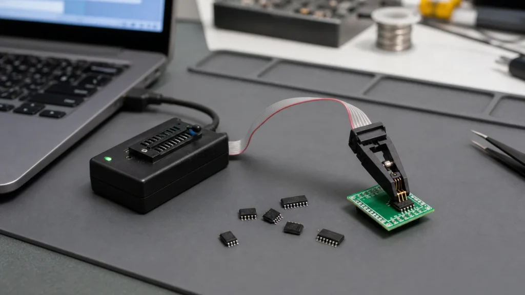
A common example is BIOS repair work. Many boards use SPI flash rather than a classic I2C EEPROM, so choosing a random “EEPROM programmer” from a marketplace listing can be misleading. ReversePCB’s guide to the CH341A programmer is relevant here because it shows how a popular low-cost tool fits real chip-burning tasks, and also why the surrounding procedure matters as much as the hardware.
Voltage is the first check, not a fine-print detail
The easiest way to damage a memory device is to treat voltage support as an afterthought. Some programmers default to 5 V behavior, some boards expose 3.3 V devices, and some modern parts require even tighter handling. A clip-on session can fail silently if the board under test is still back-powering the memory through nearby logic. Worse, a wrong voltage can overstress the chip or disturb other connected parts on the rail.
Before connecting anything, identify the target voltage from the part number and the board context. If the memory device sits next to a 3.3 V regulator, a 1.8 V translator, or a chipset rail, assume nothing. Measure where appropriate. If the programmer requires an adapter to handle low-voltage devices, use it. This is one of the places where a careful bench routine saves far more time than trying multiple combinations until one appears to respond.
In-circuit clipping versus removing the chip
Clip-on programming is attractive because it avoids hot air and soldering risk. It also introduces new failure modes. The clip can make partial contact, the board can still load the bus, and nearby protection or controller circuits can interfere with reads. If the data looks inconsistent across repeated reads, the problem may be the setup rather than the chip itself.
Removing the chip gives cleaner electrical conditions, but only if the operator can desolder and reinstall the package without lifting pads or overheating the board. On repair jobs, the right choice depends on the board value, package type, access, and the condition of the surrounding circuitry. If the board already shows thermal damage or corrosion, a neat in-circuit attempt may be safer as a first step. If the bus is heavily loaded, socket programming after removal may be the only reliable path.
That same discipline shows up in good PCB repair work. The visible memory chip is not always the root problem. A power fault, shorted controller, or damaged pull-up network can create the illusion of a bad EEPROM session when the real issue is elsewhere on the board.
How to choose a programmer for practical bench work
For light service tasks, technicians usually care about four things: supported device database, stable software, clip or adapter availability, and voltage flexibility. High-end universal programmers add speed, broad package coverage, and stronger verification features, but a modest tool can still be effective if its limitations are understood.
Match the programmer to your actual job mix. If you mostly handle SOIC-8 serial memories, prioritize clip quality and software support for common serial parts. If you work with mixed packages, adapters and socket coverage become more important. If you regularly deal with board-level recovery in production or reverse engineering, verification logging and repeatability matter more than the lowest purchase price.
Common mistakes that waste chips and time
One mistake is trusting the marketing name of the tool more than the chip identification. Another is writing to a target before creating a verified backup. A third is assuming that any successful device ID means the electrical setup is healthy. Reads can appear to work even when the signal quality is marginal, and that becomes obvious only after the write or verify stage fails.
Another common error is ignoring package orientation. Pin 1 mistakes are still one of the fastest ways to turn a routine bench task into a recovery job. If you are clipping to a board in poor lighting or rotating an adapter several times during setup, stop and label the orientation before power is applied.
Why documentation belongs in the programming workflow
The most reliable EEPROM work is documented work. Save the original dump with a board identifier and timestamp. Record the exact chip marking, the voltage assumption, the software profile used, and whether the chip was programmed in-circuit or off-board. That information matters later when the same product returns for another repair or when a second board behaves differently with what seems to be the same image.
If the memory stores parameters that interact with the rest of the design, it also helps to understand the hardware context. A quick review of the board section around the device and the overall printed circuit board function can tell you whether the data is likely generic firmware, board-specific calibration, or configuration that should not be copied blindly between units.
Final takeaway
A good EEPROM programmer is not just a USB tool with a device list. It is part of a controlled workflow that starts with identification, voltage checking, and backup discipline. Once those habits are in place, even modest programmers become much more useful and much less risky.
If you are choosing a tool, focus on support for the memory families you actually see on the bench. If you are already in the middle of a repair, slow down enough to verify the chip type, the rail voltage, the clip orientation, and the first clean dump. Those four checks prevent most of the failures that people later blame on the programmer itself.
Is an EEPROM programmer the same thing as a BIOS programmer?
Not always. Many so-called BIOS tools are really serial flash programmers, and some memory devices on boards are not classic EEPROM parts at all. Always identify the exact chip family before choosing the tool or software profile.
Can I program an EEPROM chip with a clip while it is still on the board?
Sometimes yes, but only when the board is electrically quiet enough and the chip can be read reliably in-circuit. If repeated reads do not match or the rail is being back-powered, removing the chip may be safer.
Why is voltage matching so important when using an EEPROM programmer?
Because the wrong voltage can prevent stable reads, corrupt data, or even damage the device. Check the chip requirements and use a proper adapter when the target voltage is lower than the programmer default.
What should I do before writing a replacement image?
Read and save the original contents first, ideally more than once, and compare the dumps. That backup may contain calibration data or identifiers that you cannot recover later.


