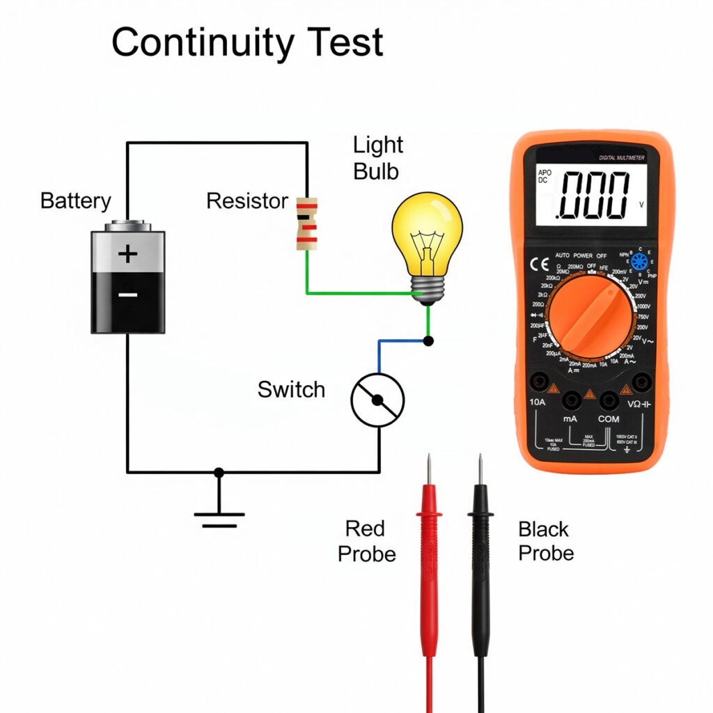
Continuity testing is a fundamental skill for anyone working with electronics. It helps determine if an electrical path is complete. This is crucial for troubleshooting circuits and ensuring their reliability.
A multimeter is an essential tool for this task. It can measure voltage, current, and resistance, and perform continuity tests. Understanding how to use it effectively can save time and prevent costly repairs.
Before you begin, it’s important to know the basics. This guide will walk you through the process step-by-step. You’ll learn how to set up your multimeter and interpret the results.
Safety is paramount when working with electrical circuits. Always ensure the circuit is de-energized before testing. With the right knowledge and precautions, continuity testing can be a straightforward and rewarding process.
What Is Continuity Testing and Why Is It Important?
Continuity testing checks if there is a complete path for current to flow in an electrical circuit. This test helps identify breaks in the circuit. A broken circuit means electricity cannot flow, leading to malfunctions.
Why is continuity testing crucial? It’s essential for ensuring the integrity of connections. Whether you’re dealing with wires, switches, or fuses, knowing the pathway is complete prevents unexpected issues.
Continuity tests are valuable in many scenarios. Here are a few key applications:
- Troubleshooting electrical problems
- Verifying the condition of fuses
- Checking the integrity of solder joints

Without continuity testing, hidden faults might go unnoticed. Regular checks maintain safety and performance. Mastering this technique provides a solid foundation for anyone involved in electronics. Remember, it aids in diagnosing and fixing problems efficiently, safeguarding the functionality of electrical systems.
Multimeter's Key Features for Continuity Testing
Knowing your multimeter is essential for accurate continuity testing. Multimeters come with various features that enhance their functionality. Familiarize yourself with these features to maximize the tool’s potential.
Your multimeter should include key elements. Continuity mode, often marked by a diode symbol, is crucial. Also, look for an audible beep which confirms a continuous path.
Here’s a quick list of desirable features in a multimeter for continuity testing:
- Audible continuity beep
- Backlit display for low-light conditions
- Auto-ranging for simplicity
- Durable casing for protection
A multimeter with these features will improve your testing experience. Ensure you understand the symbols and settings unique to your device. This understanding will make your continuity tests more effective and precise. A well-equipped multimeter simplifies troubleshooting and aids in maintaining reliable electrical connections.
Safety Precautions Before Testing Continuity
Before you begin continuity testing with a multimeter, safety is crucial. Taking preventive measures can avoid accidental damage or injury. Always prioritize safety during electrical work.
Start by ensuring the circuit is de-energized. This step is vital to prevent electrical shock and damage to the multimeter. Disconnect power supplies and double-check with a voltage tester if necessary.
Here’s a quick checklist for safety:
- Ensure the circuit is powered off
- Wear insulated gloves and use insulated tools
- Check the probes for damage
Adhering to these precautions is essential. Following them protects both you and your equipment. Regular safety checks make your continuity testing process smooth and worry-free.
A multimeter with these features will improve your testing experience. Ensure you understand the symbols and settings unique to your device. This understanding will make your continuity tests more effective and precise. A well-equipped multimeter simplifies troubleshooting and aids in maintaining reliable electrical connections.
Step-by-Step Guide to Test Continuity with Multimeter
Testing continuity with a multimeter is a simple yet essential skill. It helps you ensure your circuits and components are intact. Follow this guide for accurate results each time.
Step 1: Prepare the Multimeter and Test Leads
Start by gathering your equipment. Check the condition of your multimeter and leads. Ensure all parts are functional.
Connect the black probe to the COM port. Insert the red probe into the VΩmA port. Your multimeter is now ready to use.
Here’s a quick preparation checklist:
- Inspect multimeter for damage
- Connect probes correctly
- Ensure batteries have a charge
Step 2: Set the Multimeter to Continuity Mode
Next, set the multimeter to continuity mode. This mode is often marked by a diode symbol or sound wave icon. Adjust the rotary switch accordingly.
Make sure the display shows the continuity symbol. Your multimeter is now set for testing. Double-check your settings to avoid errors.
Step 3: Test the Circuit or Component
Now, test your circuit or component. Touch the probes to the two ends of the item being tested. Ensure firm contact for accurate readings.
If the circuit is complete, the multimeter will beep. A beep indicates continuity, meaning the current can flow. If not, check the following:
- Ensure good probe contact
- Clean test points if dirty
- Re-check circuit power status
Step 4: Interpret the Results
Interpreting results is straightforward. A continuous beep or zero reading means continuity. No beep or ‘OL’ on the display indicates a break.
In case of no continuity, inspect further for breaks. Confirm results by retesting, especially if uncertain. Typical outcomes:
- Beep: Circuit is continuous
- ‘OL’: Circuit is open
Consistent testing practices will improve accuracy. Understanding these outcomes ensures correct issue diagnosis.
Where to Use Continuity Testing?
Continuity testing with a multimeter is essential in various fields. It offers reliable diagnostics for multiple applications.
In electronics, it’s vital for checking solder joints and circuit paths. This helps prevent faults before they cause issues. Continuity tests can verify the integrity of newly assembled circuits.
In electrical repairs, continuity testing identifies faults in fuses, switches, and wires. It aids in diagnosing both short circuits and open circuits. Prompt identification of these problems can prevent further damage.
Typical Applications Include:
- Checking extension cords for damage
- Verifying switch functionality
- Testing appliance wiring connections
Testing extends to automotive repairs and home wiring projects. Understanding where to apply continuity testing can improve safety and effectiveness.
Troubleshooting Tips
Achieving precise results in continuity testing requires attention to detail. Consistent practice can help refine your skills over time.
Begin with checking the test probes for wear and damage. Damaged probes can lead to inaccurate results and frustration. It’s also important to clean the contact points to ensure a strong connection.
Ensure the multimeter is properly calibrated. An uncalibrated device may yield unreliable readings. Regular calibration can significantly enhance measurement accuracy.
Helpful Tips:
- Verify the multimeter’s battery level.
- Avoid touching metal parts while testing.
- Ensure power is off on the tested circuit.
Following these tips can help troubleshoot and rectify any issues faced during testing. Accurate continuity testing ensures reliable diagnostics across various applications.
Frequently Asked Questions
Whether it's safe to perform continuity tests on live circuits?
It’s important to always ensure the circuit is de-energized before testing. This prevents damage to the multimeter and keeps you safe.
What 'OL' on the multimeter screen means?
‘OL’ indicates an open loop, meaning there’s no continuity present in the circuit.
What does a continuous beep indicate?
A continuous beep means there’s a complete electrical path between the two points you’re testing. The resistance is very low, allowing current to flow freely.
Why is my multimeter showing no sound during testing?
If your multimeter isn’t beeping, the most common reason is an open circuit (no continuity), indicating a break in the path. Other reasons could be that the multimeter isn’t set to continuity mode, its battery is low, or the device itself is faulty.
Can I test continuity on any component?
No, you can’t. Continuity tests are mainly for checking the path in wires, fuses, and switches that should have very low resistance. It’s not for components like resistors, capacitors, diodes, or integrated circuits that need different testing methods.
Conclusion
Mastering continuity testing with a multimeter ensures your circuits are safe and dependable. This skill empowers you to quickly pinpoint issues and enhance your troubleshooting abilities.


