Voltage Drop Calculator
Accurately calculate voltage drop in electrical circuits with our comprehensive tool. Understand the formulas, applications, and solutions for optimal electrical system performance.

What is Voltage Drop?
A comprehensive explanation of voltage drop, its causes, and why it matters in electrical systems.
Definition
Voltage drop is the decrease in electrical potential as current flows through a conducting material in an electrical circuit. It is similar to the decrease in water pressure as water flows through a long pipe with friction.
Causes
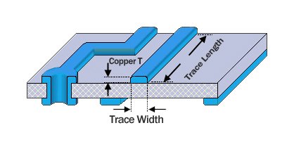
The primary cause is conductor resistance, influenced by:
- Material (copper has lower resistivity than aluminum)
- Length (longer cables mean greater resistance)
- Cross-sectional area (thinner cables have higher resistance)
Why It Matters
Excessive voltage drop can lead to equipment failure, overheating, and safety hazards. It can cause dim lights, inefficient motor operation, and even electrical fires in extreme cases.
Voltage Drop Visualization
Voltage drop across different cable lengths with constant current.
Voltage Drop Formulas
Understanding the mathematical formulas underlying voltage drop calculations for different types of circuits.
DC Circuits
ΔV = I × R
Basic DC voltage drop formula
Where:
- ΔV = Voltage drop in volts (V)
- I = Current in amperes (A)
- R = Conductor resistance in ohms (Ω)
Resistance Calculation:
R = ρ × (L/A)
- ρ = Material resistivity (Ω·m)
- L = Conductor length (m)
- A = Cross-sectional area (m²)
AC Circuits
ΔV = I × Z
Basic AC voltage drop formula
Where:
- ΔV = Voltage drop in volts (V)
- I = Current in amperes (A)
- Z = Conductor impedance in ohms (Ω)
Three-Phase Circuits:
ΔV = √3 × I × Z × L
For three-phase systems, we multiply by the square root of 3 (approximately 1.732) to account for the phase difference.
Resistivity Values for Common Conductors
| Material | Resistivity (Ω·m at 20°C) | Temperature Coefficient (°C⁻¹) |
|---|---|---|
| Copper (annealed) | 1.72 × 10⁻⁸ | 0.00393 |
| Aluminum | 2.82 × 10⁻⁸ | 0.00391 |
| Gold | 2.44 × 10⁻⁸ | 0.0034 |
| Silver | 1.59 × 10⁻⁸ | 0.0038 |
Voltage Drop Calculator
Use our interactive calculator to determine the voltage drop in your electrical circuits.
Calculation Results
Voltage Drop
0.00 V
Voltage Drop Percentage
0.00%
Remaining Voltage
0.00 V
Status
Acceptable
Industry Standards:
- Generally acceptable: ≤3%
- Maximum allowed in most cases: 5%
- Above 5%: Potential issues
Applications
How voltage drop calculations apply across various electrical systems.

Residential Electrical Systems
- Designing wiring for new appliances such as electric ovens or air conditioning units.
- Troubleshooting dim lights or malfunctioning equipment.
- Ensuring proper voltage at distant outlets in large homes.
- Planning home renovations with additional electrical loads.

Commercial & Industrial Systems
- Designing electrical distribution systems for factories with heavy machinery.
- Ensuring compliance with NEC, IEC, and other safety standards.
- Planning three-phase systems for optimal performance.
- Preventing downtime due to voltage-related equipment failures.
Advanced Topics
A deeper look at the factors affecting voltage drop and strategies to mitigate it.
Environmental Factors
Temperature Effects
As temperature increases, the resistance of most conductors (especially metals) also increases, leading to greater voltage drop.
Temperature correction formula:
Rₜ = R₀ × (1 + α × (T - T₀))
Where α is the temperature coefficient, T is the actual temperature, and T₀ is the reference temperature (usually 20°C).
Humidity & Corrosion
Humid environments can accelerate corrosion of conductors, increasing their resistance over time. Proper insulation and conduit protection are essential to minimize these effects.
Installation Conditions
Cables installed in conduits, raceways, or bundled together may experience higher temperatures due to reduced heat dissipation, increasing resistance and voltage drop.
Mitigation Strategies
Wire Size Optimization
Using larger diameter wire reduces resistance and voltage drop. The additional cost of thicker wire is often offset by energy savings and reduced maintenance.
Voltage Regulators
Automatic voltage regulators can maintain stable voltage levels despite fluctuations in the power supply. They are especially useful in remote locations or areas with unstable power grids.
Multi-Point Circuits
Distributing loads across multiple circuits rather than using a single long run can minimize voltage drop and improve system reliability.
Ready to Calculate Voltage Drop?
Use our calculator to ensure your electrical systems are safe, efficient, and compliant with industry standards.
Calculate NowEngineering checks for Voltage Drop Calculator
Before using Voltage Drop Calculator in a PCB, firmware, repair, or validation workflow, confirm the details that usually decide whether the design works reliably instead of only reading the headline specification.
Design and troubleshooting checklist
| Area | What to check | Why it matters |
|---|---|---|
| Formula inputs | Check the units, tolerance, and boundary values used by the 3 phase voltage drop calculation formula calculation | Wrong units or ideal assumptions can make a correct formula misleading |
| Circuit context | Compare the result with voltage, current, power, thermal, and safety limits on the PCB | Calculator output still needs board-level validation |
| Verification | Confirm the result with datasheet limits, simulation, or bench measurement before release | Measured behavior catches parasitics and loading effects |
These checks help connect the search intent around 3 phase voltage drop calculation formula with practical board-level decisions, component selection, and failure analysis.