About ATMEGA328P Microcontroller
The ATmega328P is a low-power CMOS 8-bit microcontroller based on the AVR enhanced RISC architecture. The chip is developed by Atmel Corporation (Microchip Technology). It has a 20MHz clock speed, 32KB of flash memory, 16-bit Timer, and 23 Programmable I/O Lines. It is commonly used in Arduino boards and other microcontroller-based projects.
ATMEGA328P Features
- High-performance, low-power AVR 8-bit microcontroller;
- Advanced RISC Architecture;
- High-endurance non-volatile memory segment;
- Power-on reset and programmable brown-out detection;
- Internally Calibrated Oscillator;
- External and Internal Interrupt Sources;
- Six sleep modes: Idle, ADC Noise Reduction, Power Conservation, Shutdown, Standby, and Standby Extended.
ATMEGA328P Parameters
- Flash memory capacity: 32KB
- SRAM: 2KB
- EEPROM memory capacity: 1KB
- Clock frequency: 20MHz
- Interface type: I2C, SPI, USART
- Supply voltage min: 1.8V max: 5.5V
- Supply Voltage Surface Mount Devices: Surface Mount
- Package Type: PDIP/TQFP
- Number of pins: 28-PDIP, 32-TQFP
- Operating temperature range: -40°C to +85°C
- Input/Output Lines: 23
- Number of ADC inputs: 8
- 8-bit Timer/Counter: 2
- 16-bit Timer/Counter: 1
- PWM: 6 channels
- Programming method: ISP, IAP, H/PV
- Simulation method: debugWIRE
ATMEGA328P Pinout
The ATMEGA328P chip has 28 general-purpose input/output (GPIO) pins, each of which can be configured as digital input or output.
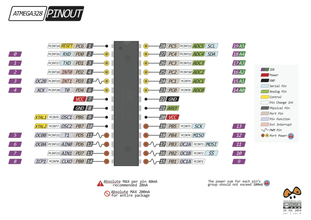
ATMEGA328P Package
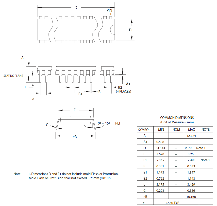
The ATmega328P is available in various package options, such as PDIP (Plastic Dual Inline Package), TQFP (Thin Quad Flat Package), and QFN (Quad Flat No-Lead). In the context of the ATmega328P microcontroller, the “P” refers to the package type of the chip. So, here the “P” specifically indicates the PDIP package.
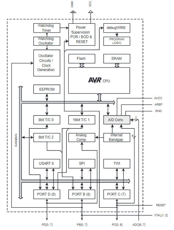
ATMEGA328P Block Diagram
How to Burn Arduino Bootloader on ATMEGA328P?
The Arduino development boards purchased sold online have been programmed with BootLoader, so you can directly use the Arduino IDE to upload programs.
However, there is no BootLoader in a new ATMEGA328P Microcontroller, so the Arduino IDE cannot be used to upload the program directly, and the program can only be programmed through ICSP.
We need to program the BootLoader for the MCU by ourselves in order to use the Arduino IDE for development.
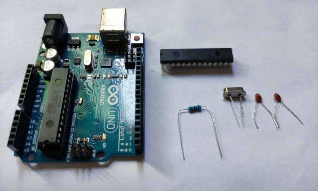
Materials Required
- ATmega328P;
- 16 MHz crystal oscillator;
- 22 pf capacitor*2;
- 10 K resistor;
- An arduino development board (Uno or nano).
Process
- Upload ArduinoISP program to the Arduino Uno;
- Wiring the ATmega328P to Arduino Uno;
- Burn BootLoader on ATmega328P;
- Test the LED Blinking program on the ATmega328P.
Step 1: Upload ArduinoISP program to the Arduino Uno
Connect the Arduino Uno development board to the computer. Find and click “File>Examples>ArduinoISP” in the Arduino software.
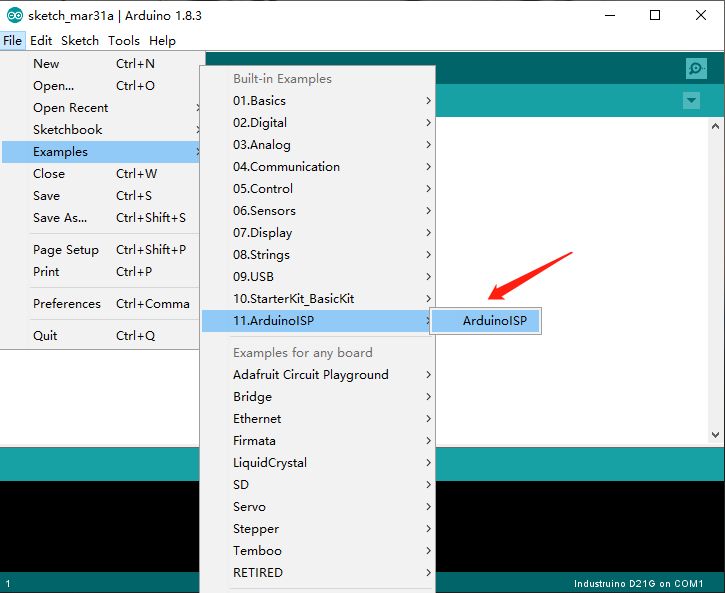
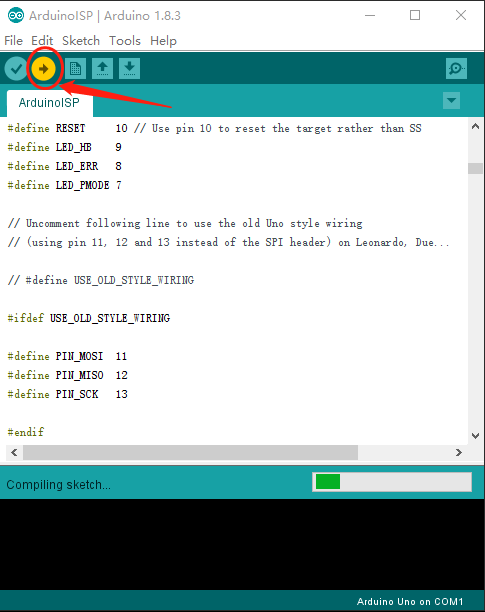
In the ArduinoISP code, you can see that the MOSI, MISO and SCK pins are defined as 11 12 13 respectively, which match the pins on the Arduino Uno development board.

Then, the settings in Tools in the IDE are as follows:
- Board: “Arduino Uno”
- Port: “COM(Arduino Uno)”
- Programmer: “Arduino as ISP”

Click the upload icon, and after a while, the ArduinoISP program will be uploaded to your Arduino Uno development board.
Step 2: Wiring the ATmega328P to Arduino Uno
According to the definition of ISP pins in the ArduinoISP code above, the wiring method and diagram between Arduino and ATmega328P are as follows:
| Arduino | ATmega328P |
|---|---|
| 10 | PIN1(RESET) |
| 11 | PIN17(MOSI) |
| 12 | PIN18(MISO) |
| 13 | PIN19(SCK) |
| GND | GND |
| VCC | VCC |

Step 3: Burn BootLoader on ATmega328P
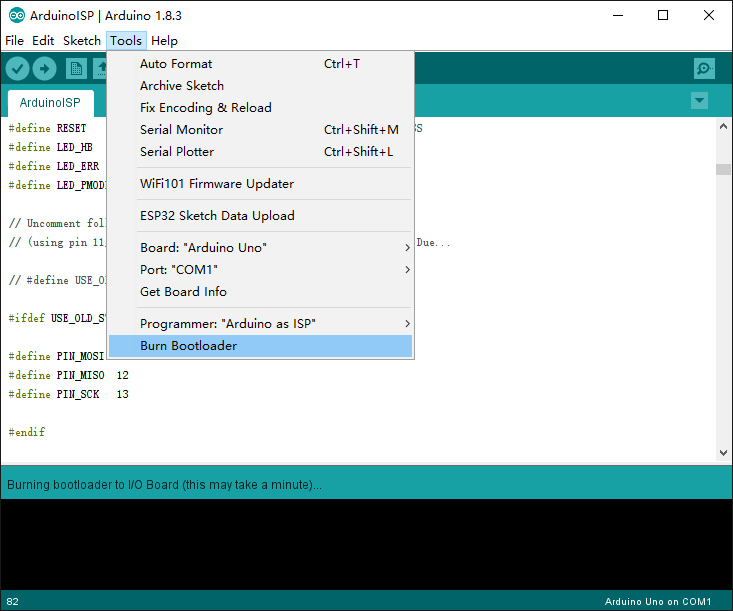
After finishing the wiring between Arduino uno and ATmega328P, we need to connect the Arduino Uno to the computer. Then click “Tools>Burn Bootloader” to burn Bootloader on ATmega328P.
Step 4: Test the LED Blinking program on the ATmega328P
Connect the positive pole of the LED to PIN2 of ATmage328P, and the negative pole to D. PIN2 of ATmega328P represents to PD0, so it is “0” in the code.
					const int LED_PIN = 2; // Define the LED pin

void setup() {
  pinMode(0, OUTPUT); // Set the LED pin as output
}

void loop() {
  digitalWrite(0, HIGH); // Turn on the LED
  delay(1000); // Wait for one second
  digitalWrite(0, LOW); // Turn off the LED
  delay(1000); // Wait for one second
}
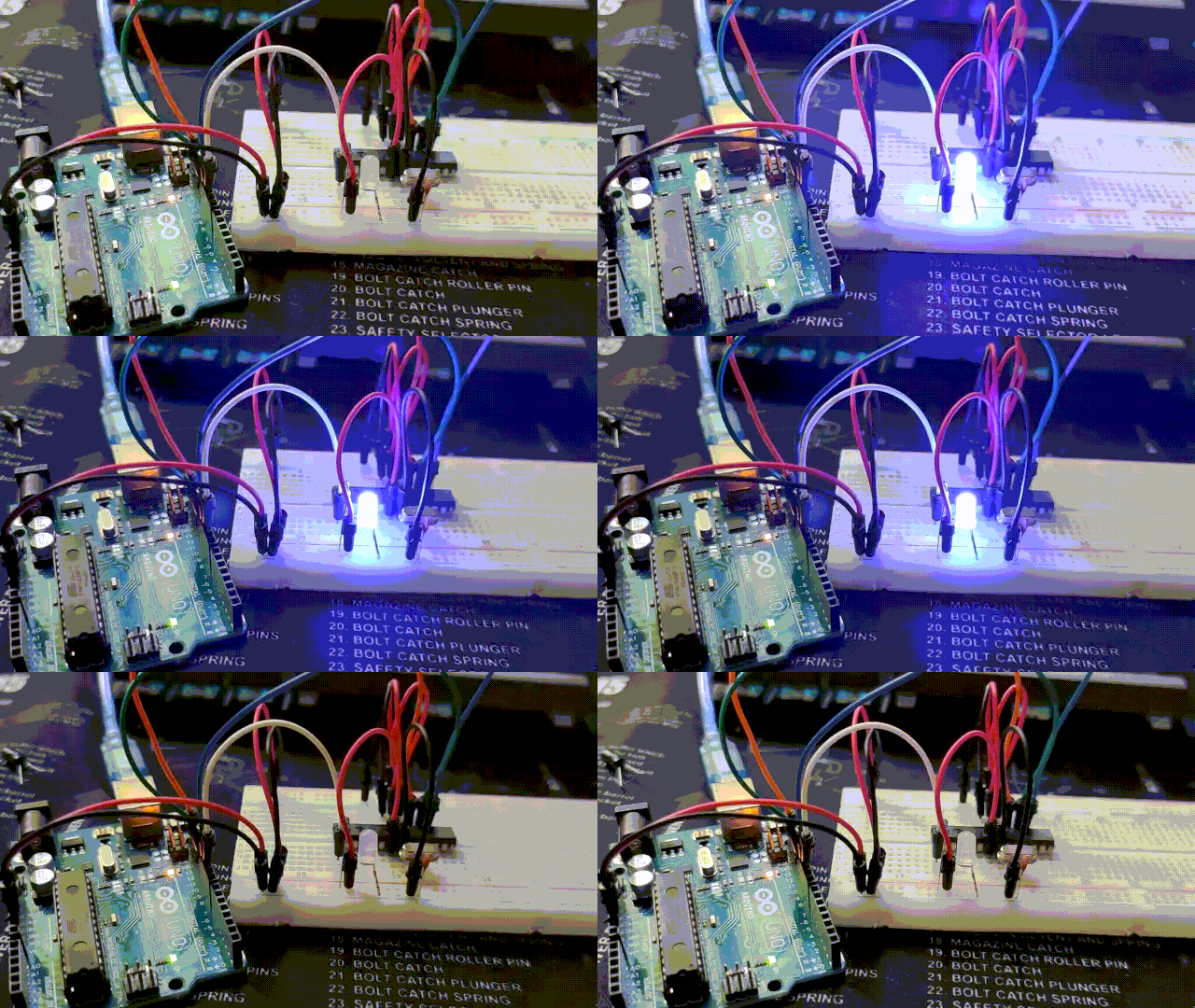
As you can see in above gif image, the LED blinking program is running normally.


