Decoding Standard PCB Board Thickness
From DIY projects to complex industrial systems, PCB thickness is a seemingly minor but critical parameter. It profoundly influences a device's mechanical strength, electrical performance, and overall design. This guide will help you understand how to choose the right PCB thickness for your project through an interactive experience.
Why It Matters
PCB thickness is not a one-dimensional decision; it is a profound choice that impacts four core areas. Click the cards below to learn more.
Mechanical Integrity
Ensures the board can withstand physical stress, preventing bending, cracking, or damage from vibration.
An appropriate thickness provides the PCB with the rigidity to resist bending, impacts, and vibrations. This is especially crucial for devices like laptops or industrial equipment that endure frequent handling and harsh environments. A board that is too thin may lead to connection failures, while one that is too thick can add unnecessary weight and bulk.
Electrical Performance
Affects signal integrity, impedance control, and heat dissipation capabilities.
In high-speed circuits, board thickness is a key determinant of transmission line impedance, and mismatched impedance can cause signal reflections and data errors. Moreover, thicker boards generally offer better heat dissipation and higher current-carrying capacity, which is vital for high-power applications.
Component Compatibility
Determines the type of components that can be mounted and the reliability of their installation.
Through-hole components, such as large capacitors and connectors, require sufficient board thickness for solid mechanical support. While surface-mount technology (SMT) components have lower thickness requirements, board thickness can still affect soldering reliability and thermal stress management for components like BGAs.
Product Design & Dimensions
Directly impacts the final product's volume, weight, and form factor.
In compact products like smartphones and wearables, every millimeter counts. Using a thinner PCB is key to achieving a lightweight and slim design. Conversely, in industrial applications where space is not an issue, durability may be prioritized, leading to the selection of a thicker board.
Interactive Thickness Explorer
There are several common PCB thicknesses. Click a bar in the chart to see typical applications and properties for that thickness.
Select A Thickness
Click on a standard thickness in the chart to the left to view its detailed information, including common applications and key advantages.
An Important Clarification: Is 1.57mm (0.062") Truly the "Standard"?
You will frequently see 1.57mm or 1.6mm mentioned. This is less of a strict official standard and more of a historical industry convention. It originated from the thickness of early plywood-based substrates and became popular due to a good balance of cost and performance. However, in modern design, the optimal thickness is solely determined by your specific application needs, not by blindly following historical practice.
Design Decision Matrix
Choosing PCB thickness is a trade-off. Select your project priorities to see relevant design considerations and recommendations.
Your Design Recommendations
Please select at least one design priority above to get tailored recommendations.
Thin vs. Thick PCBs: A Comparison
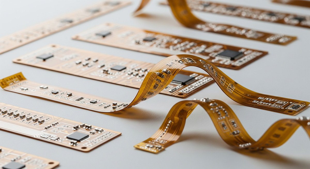
Thin PCBs (typically < 1.0mm)
Advantages:
- Lightweight: Significantly reduces product weight and shipping costs.
- Space-Saving: Ideal for compact designs like smartphones and wearables.
- Flexibility: Possesses some flexibility, which can help absorb vibration.
- Smaller Vias: Allows for smaller via sizes, which is beneficial for high-frequency designs.
Challenges:
- Low Mechanical Strength: Prone to bending or warping during assembly or use.
- Difficult to Fabricate: Very thin boards require specialized manufacturing equipment.
- Connection Reliability: Flexibility can lead to solder joint fatigue in BGA components.
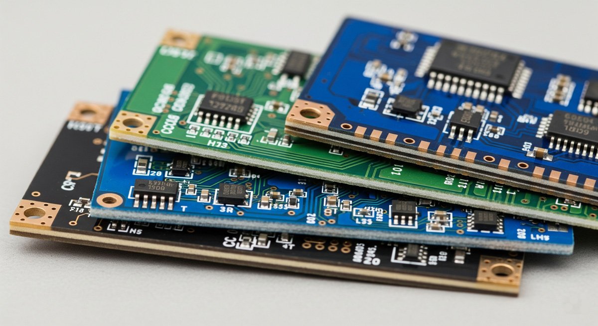
Thick PCBs (typically > 1.6mm)
Advantages:
- High Mechanical Strength: Excellent rigidity for high-stress and heavy components.
- Better Electrical Insulation: Thicker dielectric layers can withstand higher voltages.
- Superior Heat Dissipation: Greater thermal mass helps manage transient heat shocks.
- Higher Current Capacity: Thicker copper layers and traces can carry more current.
Challenges:
- Bulky: Adds to product weight and volume.
- Higher Cost: Consumes more raw materials.
- Thermal Stress: Can generate greater internal stress during thermal cycling.
Application-Specific Design Considerations
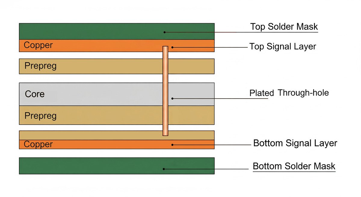
Stack-up Diagram & Impedance Control
Understanding the PCB's internal structure, or "stack-up," is critical for advanced designs. The stack-up involves layers of copper and insulating materials (prepreg, core). The thickness and material properties of these layers directly control trace impedance. Engineers precisely select these thicknesses to ensure signal integrity and prevent issues like signal reflections, especially in high-speed digital circuits.
HDI and Microvias
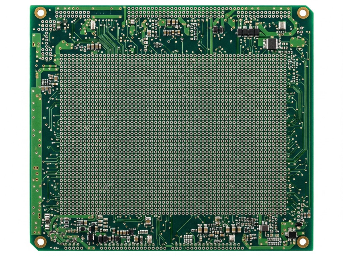
High-Density Interconnect (HDI) boards use thinner materials and advanced drilling techniques to create microvias—tiny holes connecting different layers. These are essential for miniaturized and high-performance devices, allowing for denser component placement and more complex routing in a smaller footprint.
Problem-Solution Scenarios
Scenario 1: High-Power Supply With A Thin PCB
Problem: A designer uses a thin 0.8mm board for a power supply with high current loads. The thin board and traces cannot handle the current, causing excessive heat generation. The board eventually warps and the components fail due to thermal stress.
Solution: A thicker board (2.0mm+) with thicker copper layers (2oz or 3oz) should be used. The increased thermal mass and current capacity would safely dissipate heat and provide the necessary mechanical rigidity.
Scenario 2: Compact Wearable With A Thick PCB
Problem: A designer uses a standard 1.6mm board for a new smartwatch. The board is too bulky and heavy for the compact enclosure, preventing the product from meeting its design goals for a sleek, lightweight device.
Solution: The design should be re-engineered with a thinner board (0.8mm or 1.0mm) to achieve the desired form factor. While this increases manufacturing complexity, it's essential for the product's market success.
Frequently Asked Questions (FAQ)
What is the most common standard PCB thickness?
How does PCB thickness affect mechanical strength?
What factors should I consider when choosing PCB thickness?
Conclusion & Future Outlook
Choosing the correct PCB thickness is a critical step towards a successful project. It's a complex decision that requires balancing mechanical, electrical, cost, and design goals. As technology advances, we can expect to see even thinner, more powerful PCBs in consumer electronics and new, optimized materials in high-performance applications, more effectively balancing strength, heat dissipation, and electrical performance.
We hope this guide helps you make more informed decisions in your future projects.

