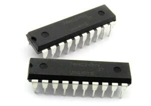
In the realm of modern electronics, Integrated Circuit (IC) board design stands as a cornerstone technology, playing a pivotal role in the creation of a vast array of devices that have become an integral part of our daily lives. From the sleek smartphones that keep us connected to the world, to the high – performance computers powering complex simulations and data processing, and the sophisticated medical equipment that aids in diagnosing and treating illnesses, IC board design is the unsung hero behind their functionality and innovation.
This article aims to provide a comprehensive exploration of the world of IC board design. Whether you’re an aspiring engineer looking to break into the field, a seasoned professional seeking to expand your knowledge, or simply someone with a curious mind interested in the inner workings of the electronics we use every day, you’ll find valuable insights here. We’ll delve into the fundamental concepts, walk through the intricate design lifecycle, clarify common terminological confusions, and discuss the latest trends and future prospects.
What is IC Board Design?
Definition
IC board design, short for Integrated Circuit board design, is the intricate process of arranging electronic components, with a primary focus on integrated circuits, and establishing their electrical interconnections on a Printed Circuit Board (PCB). This design is not just about placing components; it’s about creating a functional electronic system. Think of it as the architectural blueprint for electronic devices. Just as an architect designs a building, considering the layout of rooms, corridors, and utilities for optimal functionality, an IC board designer arranges components such as integrated circuits, resistors, capacitors, and inductors on a PCB. The goal is to ensure that electrical signals can flow smoothly between components, enabling the device to perform its intended functions, whether it’s a smartphone processing complex algorithms or a smartwatch tracking your fitness data.
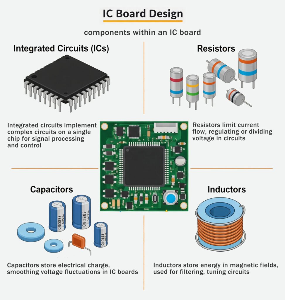
Key Components
Integrated Circuits (ICs):
These are the heart and brain of an IC board. An IC is a miniaturized electronic circuit etched onto a single semiconductor chip. It can house millions or even billions of transistors, capacitors, and resistors. For example, in a smartphone, the central processing unit (CPU) is an IC that performs all the computational tasks, from running apps to handling communication protocols. It acts as the control center, coordinating the activities of all other components on the board.
Resistors:
Resistors are used to control the flow of electric current in a circuit. They are like the traffic controllers of an IC board. By providing resistance, they can limit the amount of current passing through a particular part of the circuit. In a simple LED circuit on an IC board, a resistor is used to limit the current flowing to the LED. Without the resistor, too much current could flow, burning out the LED.
Capacitors:
Capacitors have the ability to store and release electrical energy. They are often used for filtering out unwanted electrical noise in a circuit. In the power supply section of an IC board, capacitors are used to smooth out the DC voltage. They store energy during voltage peaks and release it during dips, ensuring a stable power supply for the sensitive components on the board.
Inductors:
Inductors are coils of wire that store energy in a magnetic field when an electric current passes through them. They are commonly used in circuits to block high – frequency signals while allowing low – frequency signals to pass. In a radio – frequency (RF) circuit on an IC board, inductors are used to filter out unwanted RF interference, ensuring clear communication signals.
The IC Board Design Lifecycle
Requirement Analysis
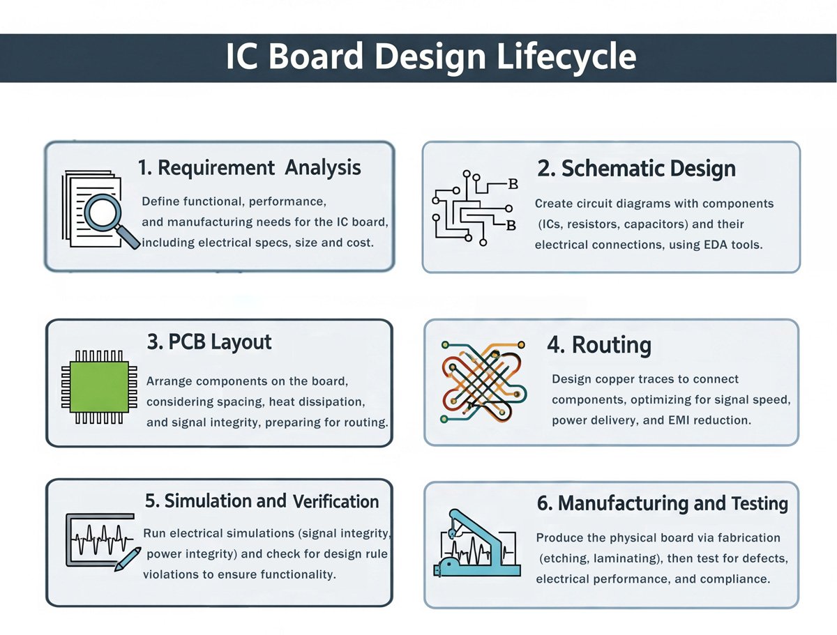
The first and a crucial stage in IC board design is requirement analysis. This phase is all about clearly defining the functional, performance, physical, and cost objectives of the IC board. For example, if you’re designing an IC board for a new smartphone, you need to consider its processing speed requirements (performance). A high – end smartphone might need a board that can support a multi – core processor running at several gigahertz to handle complex tasks like high – definition gaming and real – time video processing.
Market research plays a significant role here. By studying the current market trends, you can understand what features consumers are looking for in a particular product. If there’s a growing demand for longer – lasting battery life in wearables, the IC board design should focus on components and power management strategies that can reduce power consumption. Customer requirements also come into play. A client might have specific size constraints for an industrial control board. In such a case, the design team needs to select components and plan the layout in a way that fits within those size limits while still meeting all the functional and performance criteria. Based on these inputs, the design team selects appropriate components, determines the circuit topology, and defines module interfaces. This stage sets the foundation for the entire design process, and any oversights here can lead to costly rework later on.
Schematic Design
PCB Layout
Routing
Routing is the process of creating copper traces to establish electrical connections between components on the PCB. This is a complex task that requires strict adherence to electrical rules and physical constraints. Controlling signal integrity and power stability are also key considerations during routing. For high – speed signals, you can explore advanced routing techniques for high-speed IC boards, such as impedance matching, minimizing signal reflections, and reducing crosstalk.
Electrical rules govern aspects such as minimum trace width, clearance between traces, and the maximum length of a trace. For example, a minimum trace width might be specified based on the amount of current the trace needs to carry. A power – carrying trace that needs to handle a high current will require a wider trace to prevent overheating and voltage drops. The clearance between traces is important to avoid short – circuits. In a densely populated IC board, ensuring sufficient clearance between adjacent traces is crucial for reliable operation.
Controlling signal integrity and power stability are also key considerations during routing. For high – speed signals, techniques such as impedance matching, minimizing signal reflections, and reducing crosstalk need to be employed. Different routing strategies can be used depending on the complexity of the design. In a simple two – layer PCB, the routing might be relatively straightforward, with traces on the top and bottom layers. However, in a multi – layer PCB, which is often used in more complex designs, routing becomes more intricate. Designers need to manage different signal layers, power planes, and vias (holes that connect different layers) to ensure proper electrical connections while optimizing the use of the PCB’s real estate.
Simulation and Verification
Before moving into the manufacturing phase, it’s essential to rigorously test the design virtually through simulation and verification. This helps in identifying and rectifying potential issues early on, saving time and cost in the long run.
Simulation tools are used to analyze different aspects of the design. For electrical simulations, designers can analyze signal integrity, power integrity, and electromagnetic interference. In signal integrity simulations, they can check for issues like signal attenuation, delay, and reflections. If a high – speed data signal experiences excessive attenuation or reflections, it can lead to data errors in the final product. Thermal simulations are also crucial, especially for components that generate a significant amount of heat. By simulating the heat distribution on the IC board, designers can ensure that components are not operating at temperatures that could degrade their performance or reliability. Mechanical simulations can be carried out to assess the physical stress on the board and its components, ensuring that the design can withstand vibrations, shocks, and other mechanical forces during its intended use.
Design Rule Checks (DRC) are an important part of the verification process. These checks ensure that the design adheres to the established design rules, such as proper trace widths, clearances, and via sizes. Any violations detected during DRC need to be addressed before proceeding. By thoroughly simulating and verifying the design, designers can have greater confidence in the functionality and reliability of the final IC board product.
Manufacturing and Testing
The final stage in the IC board design lifecycle is manufacturing and testing. This is where the digital design is transformed into a physical product and put through rigorous tests to ensure its quality.
The manufacturing process begins with generating manufacturing files, such as Gerber files. These files contain all the information needed for the PCB manufacturer to fabricate the board, including the layout of the copper traces, the location of vias, and the solder mask and silkscreen layers. The PCB is then processed through several steps, including film creation, etching (removing the unwanted copper from the board), drilling holes for components and vias, plating the holes to make them electrically conductive, applying a solder mask to prevent solder from bridging between traces, and adding a silkscreen layer for component identification and other markings.
After the PCB is fabricated, components are assembled onto it. This can be done through surface – mount technology (SMT) for most modern IC boards, where components are placed directly onto the surface of the board and soldered in place. Through – hole components, although less common in modern designs, are also used in some cases, especially for larger components that require more mechanical support.
Once the board is assembled, it undergoes various tests. Electrical testing is carried out to ensure that all components are functioning correctly and that there are no short – circuits or open – circuits in the board. This can be done using techniques like flying probe testing, where a probe is used to make contact with different points on the board to measure electrical parameters. Functional testing is also crucial, where the board is tested to ensure that it performs its intended functions. For example, an IC board designed for a digital camera would be tested to ensure that it can capture images, process them, and store the data correctly. Only after passing all these tests can the IC board be considered a finished, high – quality product ready for use in the final electronic device.
Fundamental Principles for IC Board Design
Signal Integrity
Signal integrity is a crucial aspect of IC board design, especially in high – speed circuits. It refers to the ability of a signal to travel along a transmission line without significant distortion, attenuation, or interference. In simple terms, it ensures that the electrical signals on the IC board can accurately convey the intended information from the source to the destination.
Several factors can impact signal integrity. One of the main culprits is impedance mismatch. When the impedance of the source, the transmission line (such as a copper trace on the PCB), and the load are not properly matched, signal reflections occur. For example, if the impedance of a trace is 50 ohms, but the load has an impedance of 100 ohms, part of the signal will be reflected back towards the source. This reflection can cause overshoots, undershoots, and ringing in the signal waveform, as shown in the figure below. Overshoots are when the signal voltage exceeds the normal high – level voltage, and undershoots are when it dips below the normal low – level voltage. Ringing is the oscillation of the signal around the desired level. These issues can lead to incorrect data transmission and unreliable circuit operation.
Another factor affecting signal integrity is crosstalk. Crosstalk occurs when electromagnetic fields from one signal – carrying trace couple with an adjacent trace, inducing unwanted signals. In a densely populated IC board, where traces are close to each other, crosstalk can be a significant problem. For instance, in a high – speed data bus, if the clock signal trace runs too close to the data signal traces, the high – frequency components of the clock signal can interfere with the data signals, causing bit – errors in the data transmission.
To maintain good signal integrity, designers employ several techniques. Controlling impedance is key. This can be achieved by carefully calculating and adjusting the width of the copper traces, the distance between traces, and the thickness of the PCB layers. In high – speed designs, impedance – matching components such as resistors can be added at the source or load ends to ensure that the impedance of the entire signal path is consistent. For example, a 50 – ohm resistor can be placed at the load end of a 50 – ohm impedance trace to prevent signal reflections.
Minimizing signal delay is also important. This can be done by keeping the length of the signal traces as short as possible, especially for high – speed signals. Using techniques like differential signaling, where two complementary signals are transmitted on adjacent traces, can also help reduce the impact of noise and interference, improving signal integrity. In a high – speed serial communication interface, differential signaling is often used to transmit data over long distances with high reliability.
Power Integrity
Power integrity is essential for the proper functioning of an IC board, as it ensures that all components on the board receive a stable and clean power supply. In modern electronic devices, especially those with high – speed and high – power components, maintaining power integrity has become increasingly challenging.
The importance of power integrity can be seen in its impact on component performance. For example, in a high – performance microprocessor, even small fluctuations in the power supply voltage can lead to errors in data processing, decreased clock speed, or even system crashes. A stable power supply is crucial for the proper operation of sensitive analog components as well. In an audio amplifier circuit, power supply noise can introduce unwanted hum or distortion in the audio output.
One of the main aspects of power integrity is designing a robust power distribution network (PDN). This involves creating a network of power planes (such as the VCC and GND planes in a PCB) and interconnecting traces that can efficiently deliver power to all components on the board. The PDN should be designed to have low impedance, especially at high frequencies, to minimize voltage drops and power losses. For example, using multiple power planes and adding vias to connect different layers can help reduce the resistance and inductance in the power delivery path.
Reducing power noise and voltage fluctuations is another critical task. Power noise can be caused by various factors, such as the switching of power – hungry components like DC – DC converters or the simultaneous switching of multiple digital components. To mitigate power noise, designers use techniques like adding decoupling capacitors. Decoupling capacitors act as local energy reservoirs, providing additional current when the power demand of a component suddenly increases. Small ceramic capacitors (in the range of picofarads) are typically placed very close to the power pins of components to filter out high – frequency noise, while larger electrolytic capacitors (in the range of microfarads) are used to handle low – frequency power fluctuations.
In addition, proper grounding is essential for power integrity. A good ground plane serves as a reference for the power supply and helps in reducing electromagnetic interference. It also provides a low – impedance path for the return current, which is crucial for maintaining stable power delivery. By implementing these strategies, designers can ensure that the IC board has a reliable power supply, enabling all components to operate at their optimal performance levels.
Thermal Management
Thermal management is a vital consideration in IC board design, as components generate heat during operation, and excessive heat can lead to performance degradation, reduced lifespan, and even component failure. In modern electronic devices, which are becoming more compact and power – dense, effective thermal management has become increasingly challenging.
Components such as high – power integrated circuits, power transistors, and high – performance processors generate a significant amount of heat. For example, a high – end graphics processing unit (GPU) in a gaming computer can dissipate several hundred watts of power as heat. If this heat is not properly managed, the temperature of the components can rise to levels where the electrical characteristics of the semiconductor materials change, leading to increased resistance, decreased mobility of charge carriers, and ultimately, a decrease in the performance of the component.
To prevent overheating, several thermal management techniques are employed. Strategic component placement is the first step. Components that generate a lot of heat should be placed in areas with good ventilation or near heat sinks. Heat sinks are metal structures with fins that increase the surface area available for heat dissipation. They are often made of materials with high thermal conductivity, such as aluminum or copper. For example, in a computer motherboard, the CPU is usually placed near a large heat sink, and a thermal paste is applied between the CPU and the heat sink to improve the thermal contact.
Using thermal vias is another effective technique. Thermal vias are holes in the PCB that are filled with a conductive material, such as copper. They connect different layers of the PCB and help in transferring heat from components on one layer to other layers, where it can be dissipated more effectively. In a multi – layer PCB, thermal vias can create a thermal path that allows heat to spread across the board, reducing the temperature gradient and preventing hotspots.
Copper pours are also used for thermal management. A copper pour is an area of solid copper on the PCB that can act as a heat spreader. By increasing the amount of copper on the board, more heat can be conducted away from the components. Copper has a high thermal conductivity, which makes it an ideal material for heat dissipation. In addition, proper ventilation and the use of fans can help in removing the heat from the IC board. In a server chassis, multiple fans are often used to circulate air and cool down the components.
Electromagnetic Compatibility (EMC)
Electromagnetic compatibility (EMC) refers to the ability of an IC board to function correctly in its intended electromagnetic environment without causing or being affected by electromagnetic interference (EMI). In today’s highly interconnected and electronically-dense world, EMC has become a critical aspect of IC board design. For a more detailed guide on achieving EMC compliance in complex PCB layouts, designers can employ several design measures.
When an IC board does not meet EMC requirements, it can cause a variety of problems. For example, it can interfere with other electronic devices in its vicinity. In a car, if the IC board in the infotainment system does not have proper EMC design, it can interfere with the radio reception, causing static or distortion in the audio. On the other hand, the IC board can also be affected by external electromagnetic sources, such as radio frequency signals from mobile phones or electromagnetic fields generated by power lines. This can lead to malfunctions in the IC board, such as incorrect data processing, false triggering of components, or even system failures.
To ensure EMC, several design measures can be taken. Shielding is one of the most common techniques. Shielding involves enclosing the IC board or sensitive components within a conductive enclosure, such as a metal box or a metal – coated plastic case. The shielding material acts as a barrier, blocking electromagnetic waves from entering or leaving the enclosed area. For example, in a high – frequency communication module, the circuit board is often shielded to prevent interference from external radio – frequency signals.
Proper grounding is also crucial for EMC. A good ground connection provides a low – impedance path for the return of electromagnetic currents, reducing the likelihood of electromagnetic radiation. It also helps in preventing the build – up of static charges, which can cause electrostatic discharge (ESD) events. ESD can damage components on the IC board, especially sensitive semiconductor devices. In addition, filtering can be used to remove unwanted electromagnetic signals. Filters are electronic components, such as capacitors and inductors, that are designed to block or attenuate certain frequencies of electromagnetic waves. For example, a low – pass filter can be used to block high – frequency noise from entering the power supply lines of an IC board.
Design for Manufacturability (DFM)
Design for Manufacturability (DFM) is an approach that focuses on considering the manufacturing process and capabilities during the design phase of an IC board. It is essential because it can significantly impact the cost, quality, and production efficiency of the final product.
If DFM principles are not followed, it can lead to various issues during manufacturing. For example, if the trace width on the PCB is too narrow, it can be difficult for the manufacturing equipment to accurately etch the copper traces, resulting in open circuits or inconsistent trace widths. Similarly, if the clearance between components is too small, it can cause problems during the soldering process, such as solder bridges between adjacent components. These manufacturing defects can increase the production cost, as defective boards need to be reworked or discarded. They can also lead to reliability issues in the final product.
To implement DFM, designers need to adhere to manufacturing tolerances. This means ensuring that all design parameters, such as trace width, hole size, and component spacing, are within the acceptable range specified by the manufacturer. For example, if the manufacturer has a minimum trace width tolerance of 0.1 mm, the designer should ensure that all traces are at least 0.1 mm wide to avoid manufacturing difficulties.
Optimizing component placement is another important aspect of DFM. Components should be placed to streamline the manufacturing process. For example, placing components in a grid pattern can make it easier for automated pick – and – place machines to accurately place the components on the PCB. In addition, components that are frequently used or are likely to be replaced should be placed in easily accessible areas.
Choosing the right manufacturing process is also crucial. Different manufacturing processes have different capabilities and limitations. For example, surface – mount technology (SMT) is more suitable for high – density and high – volume production, as it allows for smaller component sizes and faster assembly. Through – hole technology, on the other hand, may be more appropriate for components that require mechanical support or for applications where the board needs to be more rugged. By considering these factors during the design phase, designers can ensure that the IC board can be efficiently and cost – effectively manufactured, resulting in a high – quality final product.
Essential Tools for IC Board Design
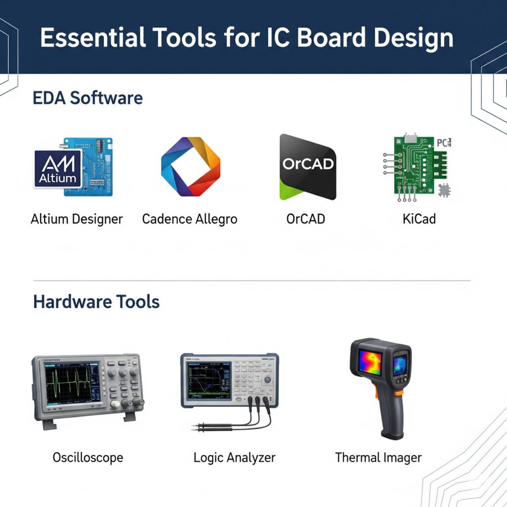
Electronic Design Automation (EDA) Software
Electronic Design Automation (EDA) software is the cornerstone of modern IC board design, playing an indispensable role throughout the entire design process. These powerful tools have revolutionized the way engineers approach IC board design, replacing manual and time – consuming design methods with highly efficient digital workflows. To learn more about selecting the right tools for your project, consider choosing the right EDA software based on your specific needs. Here are some of the most commonly used EDA software in the industry: Altium Designer, Cadence Allegro, OrCAD, and KiCad.
Altium Designer:
Altium Designer is a comprehensive and highly integrated EDA software that has gained widespread popularity among engineers. It offers a unified design environment that seamlessly integrates schematic design, PCB layout, and signal integrity analysis. This integration allows designers to easily switch between different design stages, ensuring a smooth and efficient design process. For example, when making changes to the schematic, the PCB layout is automatically updated, reducing the risk of errors and saving time.
Altium Designer also boasts an extensive and user – customizable component library, providing designers with access to a vast range of electronic components. This library can be further enhanced by importing user – created components or third – party libraries, giving designers the flexibility to work with the components they need for their specific projects. Additionally, its advanced 3D design capabilities enable designers to visualize the physical layout of the PCB in three dimensions, helping them to identify potential issues related to component placement and mechanical interference early in the design process.
Cadence Allegro:
Cadence Allegro is a professional – grade EDA software that is renowned for its exceptional capabilities in handling complex and high – end IC board designs. It is particularly well – suited for projects that involve high – speed signals, such as those found in high – performance computing, telecommunications, and aerospace applications. Allegro offers advanced routing techniques, including differential pair routing and impedance – controlled routing, which are crucial for ensuring signal integrity in high – speed circuits.
Its powerful constraint management system allows designers to define and enforce strict electrical, physical, and thermal constraints, ensuring that the final design meets all the required specifications. Moreover, Cadence Allegro excels in collaborative design, enabling multiple designers to work on the same project simultaneously. This feature is essential for large – scale projects where teamwork and efficient communication are key to success.
OrCAD:
OrCAD is a widely used EDA software that is known for its powerful simulation capabilities and user – friendly interface. It provides a comprehensive suite of tools for circuit design, simulation, and analysis. In the schematic design phase, OrCAD offers a wide range of components and symbols, making it easy for designers to create accurate and detailed circuit diagrams. The software’s simulation capabilities are particularly impressive, allowing designers to simulate the behavior of their circuits under various conditions.
For example, they can perform AC analysis, DC analysis, transient analysis, and more to evaluate the performance of their designs. This helps in identifying potential issues and optimizing the circuit design before moving on to the PCB layout stage. OrCAD also has a strong integration with other Cadence tools, providing a seamless workflow for designers who require a more comprehensive design solution.
KiCad:
KiCad is an open – source EDA software that has gained significant popularity in recent years, especially among hobbyists, students, and small – scale developers. One of its most appealing features is its completely free – of – charge nature, making it an accessible option for those with limited budgets. Despite being open – source, KiCad offers a comprehensive set of features that can meet the needs of many IC board design projects. It includes a schematic editor, a PCB layout editor, and 3D viewing capabilities.
The software has a growing and active community, which contributes to its development and provides support to users. This community – driven development model ensures that KiCad is constantly evolving, with new features and improvements being added regularly. Users can also benefit from the shared knowledge and experience of the community, accessing tutorials, forums, and user – contributed libraries to enhance their design process.
Other Tools
In addition to EDA software, several other tools are essential for IC board design and testing. These tools help engineers to verify the functionality and performance of their designs, identify and troubleshoot issues, and ensure that the final product meets the required standards.
Oscilloscopes:
Oscilloscopes are fundamental tools in the field of electronics for observing and analyzing electrical signals. They display the voltage waveform of an electrical signal over time, allowing engineers to measure various parameters such as amplitude, frequency, and phase. In IC board design, oscilloscopes are used to debug circuits, verify the integrity of signals, and analyze the performance of components. For example, when testing a high – speed serial interface on an IC board, an oscilloscope can be used to measure the signal rise and fall times, jitter, and signal levels. This information is crucial for ensuring that the interface is operating within the specified parameters and that the data is being transmitted accurately.
Logic Analyzers:
Logic analyzers are specialized tools for capturing and analyzing digital signals. They can simultaneously capture multiple digital signals and display them in a logical format, making it easy to analyze the timing relationships between different signals. In IC board design, logic analyzers are often used to debug digital circuits, such as microcontrollers, FPGAs, and digital communication interfaces. For instance, when developing a new firmware for a microcontroller – based system on an IC board, a logic analyzer can be used to monitor the communication between the microcontroller and other components, such as sensors or memory chips. This helps in identifying issues such as incorrect data transmission, timing errors, and bus contention.
Thermal Imagers:
Thermal imagers are devices that detect infrared radiation and convert it into a visible image, allowing users to visualize the temperature distribution of an object or a surface. In IC board design, thermal imagers are used to analyze the thermal performance of components and the overall board. They can help in identifying components that are overheating, detecting hotspots on the PCB, and evaluating the effectiveness of thermal management solutions. For example, in a high – power IC board, a thermal imager can be used to check if the heat sinks are effectively dissipating heat from the components. If a component is operating at a higher – than – expected temperature, it could lead to performance degradation or even failure, and a thermal imager can help in pinpointing the source of the problem.
Comparison: IC Board Design vs. System-in-Package (SiP)
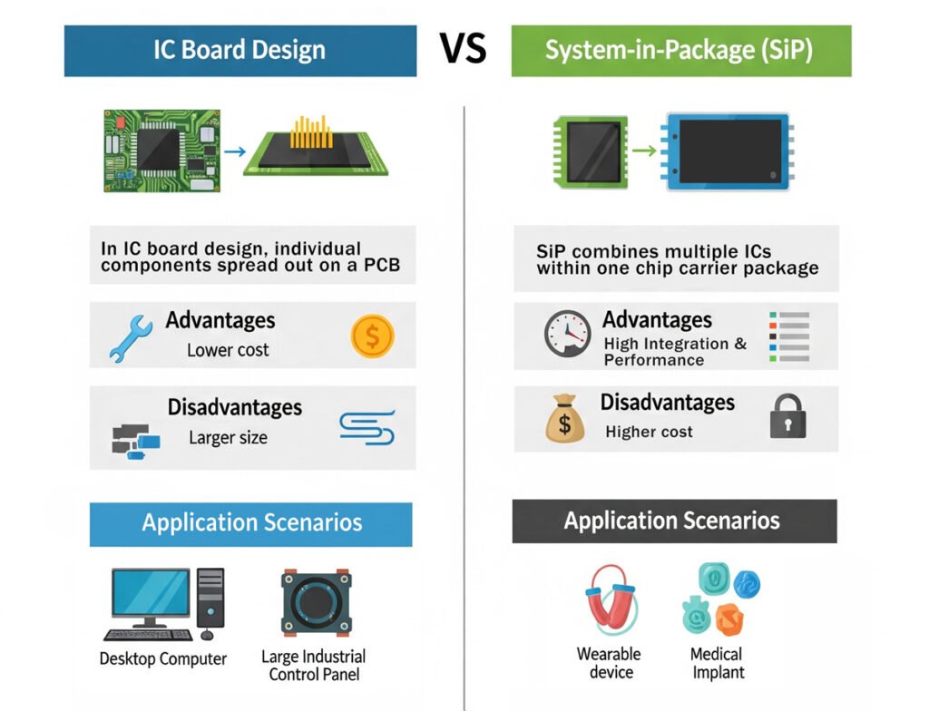
Definitions
IC board design, as we’ve explored in detail, is the process of arranging components on a printed circuit board to create a functional electronic system. It focuses on the layout and interconnection of various components, with integrated circuits being a central part.
System – in – Package (SiP), on the other hand, is an advanced packaging technology. It integrates multiple integrated circuits (ICs) and their supporting passive components, such as resistors, capacitors, and inductors, into a single, compact package. Instead of having individual components spread out on a PCB, SiP combines them within one chip carrier package. For example, in a smartwatch, a SiP might integrate the microcontroller, the Bluetooth communication chip, and the power management IC, along with some passive components, all within a single, small package. This integration allows for a more compact and efficient solution compared to a traditional IC board design where these components would be separately placed on a PCB.
Advantages and Disadvantages
SiP Advantages:
- High Integration: SiP can integrate multiple different – function chips, which significantly reduces the overall size and complexity of the electronic system. For instance, in a smartphone, integrating the audio amplifier, power management unit, and some signal processing chips into a SiP can free up a large amount of space on the main PCB, allowing for a slimmer device design.
- Improved Performance: With shorter signal paths between the integrated chips, SiP can achieve better electrical performance. Signals can travel faster and with less interference, which is crucial for high – speed applications. In high – performance computing, SiP can enable faster data transfer between different components within the package, enhancing the overall system speed.
- Faster Time – to – Market: Since SiP simplifies the overall system design by providing a single, pre – integrated module, it can reduce the development time for the end – product. Companies can quickly integrate a SiP into their product designs without having to spend a lot of time on complex PCB layout and component integration.
SiP Disadvantages:
- Higher Cost: The manufacturing process of SiP is more complex, involving advanced techniques like die stacking, flip – chip bonding, and wire bonding. This complexity leads to higher production costs. For small – scale production or cost – sensitive applications, the cost of SiP might be a deterrent.
- Limited Design Flexibility: Once the components are integrated into a SiP, it becomes difficult to make changes to the individual components. If a particular component within the SiP needs to be updated or replaced, the entire SiP might need to be redesigned, which can be time – consuming and costly.
IC Board Design Advantages:
- Flexibility: IC board design offers great flexibility. Designers can choose from a wide range of components and can easily make changes to the design during the development process. For example, if a new component becomes available in the market, it can be easily integrated into the IC board design without major overhauls.
- Cost – Effective for Low – Volume Production: For small – scale or custom – made products, IC board design can be more cost – effective. The cost of manufacturing a custom PCB is relatively lower compared to the high – volume manufacturing required for SiP.
IC Board Design Disadvantages:
- Larger Size: In general, IC board designs tend to be larger in size compared to SiP – based solutions. The separate placement of components on a PCB takes up more space, which might not be suitable for applications where miniaturization is a key requirement, such as in wearable devices.
- Complexity in High – Density Designs: As the number of components and the complexity of the circuit increase, IC board design can become very challenging. Managing signal integrity, power distribution, and thermal management in a high – density IC board can be difficult and requires advanced design techniques.
Application Scenarios
- SiP Applications:
- Wearable Devices: In smartwatches, fitness trackers, and hearables, SiP is highly preferred. These devices require a high degree of miniaturization, and SiP can meet this requirement by integrating multiple functions into a small package. For example, a smartwatch needs to have a microcontroller, a Bluetooth module, a heart – rate sensor interface, and power management all in a compact space. A SiP can integrate these components, enabling a sleek and lightweight design.
- 5G Communication Devices: 5G devices demand high – speed data transfer and low latency. SiP can integrate multiple communication chips, such as RF transceivers, power amplifiers, and baseband processors, to achieve better performance. In 5G smartphones, SiP helps in reducing the size of the communication module while improving its performance.
- Wearable Devices: In smartwatches, fitness trackers, and hearables, SiP is highly preferred. These devices require a high degree of miniaturization, and SiP can meet this requirement by integrating multiple functions into a small package. For example, a smartwatch needs to have a microcontroller, a Bluetooth module, a heart – rate sensor interface, and power management all in a compact space. A SiP can integrate these components, enabling a sleek and lightweight design.
- IC Board Design Applications:
- Industrial Control Systems: Industrial control systems often require a high degree of customization and flexibility. IC board design allows engineers to select components based on the specific requirements of the system. For example, in a factory automation system, the IC board can be designed to interface with different types of sensors, actuators, and communication protocols. The ability to easily make changes to the design also makes it suitable for industrial applications where the system might need to be updated or modified over time.
- Prototyping and Small – Scale Production: When developing a new product in the initial stages or for small – scale production runs, IC board design is a cost – effective choice. Start – up companies or research institutions can quickly create a prototype using IC board design techniques without having to invest in the high – cost manufacturing processes required for SiP.
- Industrial Control Systems: Industrial control systems often require a high degree of customization and flexibility. IC board design allows engineers to select components based on the specific requirements of the system. For example, in a factory automation system, the IC board can be designed to interface with different types of sensors, actuators, and communication protocols. The ability to easily make changes to the design also makes it suitable for industrial applications where the system might need to be updated or modified over time.
Case Studies
Case 1: High - Speed IC Board Design for a Data Center Server
In the world of data centers, high – speed IC board design is crucial for ensuring the efficient operation of servers. One such case involved a leading data center equipment manufacturer that was developing a new generation of servers to meet the ever – increasing demands for data processing and storage.
- High – Speed Signal Integrity: The server was designed to handle high – speed data transfer rates, with data buses operating at speeds of up to 10 Gbps. Ensuring signal integrity at such high speeds was a major challenge. The long signal traces on the large – sized IC board, as well as the presence of multiple components and vias, could cause signal attenuation, reflections, and crosstalk.
- Power Management: The high – performance components in the server, such as multi – core processors and high – capacity memory modules, required a significant amount of power. Designing a power distribution network that could deliver stable power to all components while minimizing power losses and voltage fluctuations was essential.
- Thermal Management: With the high – power components operating continuously, heat generation was a major concern. The data center environment, which often has multiple servers in close proximity, exacerbates the heat – dissipation problem.
- Signal Integrity: The design team used advanced EDA tools to simulate the signal behavior on the IC board. They carefully calculated and adjusted the impedance of the signal traces, ensuring that they were properly matched to the source and load. For example, they used impedance – controlled microstrip and stripline traces. To reduce crosstalk, they increased the spacing between critical signal traces and used ground planes as shields. They also optimized the layout of components and vias to minimize signal path lengths.
- Power Management: A multi – layer power distribution network was designed, with dedicated power planes for different voltage levels. Decoupling capacitors were placed strategically close to the power pins of components to filter out high – frequency power noise. In addition, the design team implemented a power – on sequencing mechanism to ensure that components received power in the correct order, preventing power – related issues during startup.
- Thermal Management: The IC board was designed with a large number of thermal vias to transfer heat from the components to the different layers of the PCB. High – performance heat sinks were installed on the critical components, such as the processors and memory modules. The data center’s cooling system was also optimized, with improved air circulation and temperature control.
- Performance: The new server achieved a significant improvement in data processing speed. The high – speed data transfer was reliable, with a low bit – error rate. The server was able to handle a large number of concurrent data requests, meeting the demands of modern data – intensive applications such as big data analytics and cloud computing.
- Reliability: The server’s power management system ensured stable operation, with minimal power – related failures. The effective thermal management reduced the operating temperature of the components, increasing their lifespan and reliability. The server’s mean – time – between – failures (MTBF) was significantly increased, reducing the need for maintenance and downtime in the data center.
Case 2: Miniaturized IC Board Design for a Wearable Device
Challenges:
- Miniaturization: The goal was to create a sleek and lightweight smartwatch. This required packing all the necessary components, including a microcontroller, a Bluetooth module, a heart – rate sensor, and a power management unit, onto a small – sized IC board. The challenge was to find a way to reduce the size of the board without sacrificing functionality.
- Power Efficiency: Wearable devices are battery – powered, and users expect long – lasting battery life. The components on the IC board needed to be power – efficient, and the overall power consumption of the board had to be minimized.
- Sensor Integration: The smartwatch needed to integrate multiple sensors, such as an accelerometer, a gyroscope, and a heart – rate sensor. Ensuring that these sensors could operate accurately and communicate effectively with the other components on the board was a challenge.
- Miniaturization: The design team used advanced packaging technologies, such as System – in – Package (SiP) and chip – scale packaging (CSP). The SiP technology allowed them to integrate multiple components, like the microcontroller and the Bluetooth module, into a single, compact package. They also optimized the PCB layout, leveraging the role of high-density interconnect (HDI) technology in miniaturized IC board design to increase the wiring density and reduce the size of the board
- Power Efficiency: Low – power components were selected for the IC board. For example, a low – power microcontroller was chosen that could operate in different power – saving modes. The power management unit was designed to efficiently manage the power supply to all components, reducing power consumption during idle periods. A smart power – on/off mechanism was implemented to ensure that components were powered only when needed.
- Sensor Integration: The design team used a combination of analog – to – digital converters (ADCs) and signal – conditioning circuits to interface the sensors with the microcontroller. They also developed custom firmware to manage the data acquisition and processing from the sensors. To reduce interference between the sensors and other components, proper shielding and grounding techniques were employed.
- Compact Design: The new smartwatch was significantly smaller and lighter than its predecessors. The sleek design made it more comfortable for users to wear, and it also had a more appealing appearance.
- Long – Lasting Battery Life: The power – efficient design of the IC board resulted in a longer – lasting battery. Users could now use the smartwatch for several days on a single charge, improving the overall user experience.
- Accurate Sensor Data: The integrated sensors provided accurate data for various functions, such as fitness tracking and activity monitoring. The smartwatch could accurately measure heart rate, steps taken, and sleep patterns, meeting the expectations of fitness – conscious users.
Future Trends in IC Board Design
The Role of AI in EDA
Advanced Packaging Technologies
The development of advanced packaging technologies is constantly evolving, and they are having a profound impact on IC board design. These technologies are enabling smaller, more powerful, and more efficient IC boards, which are essential for the development of modern electronic devices. One of the most promising advanced packaging technologies is 3D packaging. Fan – out packaging is another advanced technology that is gaining popularit
The Development of Flexible and Stretchable PCBs
Conclusion
IC board design is the backbone of modern electronics, influencing every aspect of the devices we use daily. From the initial requirement analysis to the final manufacturing and testing, each stage in the design lifecycle is crucial. Understanding fundamental principles like signal integrity, power integrity, thermal management, EMC, and DFM is essential for creating high – performance and reliable IC boards.
The tools of the trade, especially EDA software, have evolved to support the complex design processes. Comparing IC board design with SiP shows the different design approaches available, each with its own set of advantages and application scenarios. Case studies demonstrate how real – world challenges are overcome in IC board design to meet the demands of high – speed data transfer and miniaturization.
Looking ahead, trends like the integration of AI in EDA, the development of advanced packaging technologies, and the emergence of flexible and stretchable PCBs promise to revolutionize the field. As technology continues to evolve, there is always more to learn and explore in IC board design. Whether you’re a professional in the field or just starting to be interested, there are countless opportunities to deepen your knowledge and contribute to the ever – advancing world of electronics. So, keep learning, keep innovating, and be a part of the exciting journey of IC board design!

