What is MCP2515?
MCP2515 is a standalone Controller Area Network (CAN) protocol controller developed by Microchip. It fully implements the CAN 2.0B specification, providing a reliable, flexible, and cost-effective CAN bus communication solution for embedded systems via a high-speed SPI interface.
MCP2515 Core Technical Specifications
- CAN Protocol: CAN 2.0B compliant
- Max Bitrate: 1 Mbps
- MCU Interface: SPI (up to 10 MHz)
- Voltage: 2.7V - 5.5V
- Typical current: 5 mA (active), 1 µA (standby)
- Receive Buffers: 2
- Transmit Buffers: 3
- Filters / Masks: 6 / 2
- Operating Temperature: -40°C to +125°C
Interactive Architecture Diagram
Hover over a module to see details
MCP2515 Physical and Pinout
A photo of the physical chip and a diagram of its pin configuration.
MCP2515 integrated circuit chip | Photo by Microchip
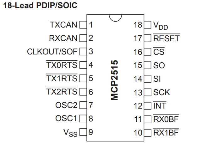
MCP2515 Standalone CAN Controller Pin Diagram
How It Works Internally
The MCP2515 simplifies CAN communication for microcontrollers that lack a native CAN module. It acts as an intermediary, handling the complex tasks of the CAN protocol so the MCU only needs to send and receive data via the SPI interface. The MCP2515's internal clock synchronizes with the bus, and its dedicated hardware manages bit timing, error checking, and message buffering, significantly reducing the MCU's processing load and freeing it for other tasks.
A Guide for Beginners and Hobbyists
This section guides you through the basic hardware connections and programming for using the MCP2515 with Arduino or ESP32.
Hardware Connection and Wiring
Here is a typical wiring diagram for connecting an MCP2515 module to an Arduino Uno. Remember that two 120Ω termination resistors are required at each physical end of the CAN bus.
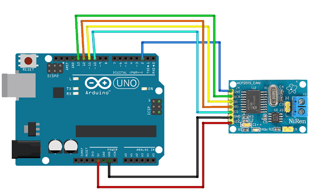
Wiring diagram showing how to connect an Arduino Uno to an MCP2515 CAN bus module
MCP2515 Module Pinout:
- VCC: Power supply (5V)
- GND: Ground
- CS: Chip Select for SPI (e.g., Arduino D10)
- SO: SPI Data Out (MISO, e.g., Arduino D12)
- SI: SPI Data In (MOSI, e.g., Arduino D11)
- SCK: SPI Clock (e.g., Arduino D13)
- INT: Interrupt (optional, e.g., Arduino D2)
- CAN_H / CAN_L: CAN bus high/low lines
Software: Sending and Receiving
The following code snippets demonstrate how to send and receive a simple message using the `mcp2515` library.
Initialization and Sending
#include <mcp2515.h>
#include <SPI.h>
#define CAN_INT 2
#define CS_PIN 10
MCP2515 mcp2515(CS_PIN);
void setup() {
  Serial.begin(115200);
  SPI.begin();
  if (mcp2515.reset() != MCP2515::ERROR_OK) {
    Serial.println("Error initializing MCP2515");
    while(1);
  }
  if (mcp2515.setBitrate(CAN_125KBPS) != MCP2515::ERROR_OK) {
    Serial.println("Bitrate setting error");
    while(1);
  }
}
void loop() {
  CanMessage msg;
  msg.id = 0x123;
  msg.data[0] = 0xAA;
  msg.data_length_code = 1;
  mcp2515.sendMessage(&msg);
  Serial.println("Message sent!");
  delay(1000);
}
Receiving a Message
#include <mcp2515.h>
#include <SPI.h>
#define CS_PIN 10
MCP2515 mcp2515(CS_PIN);
void setup() {
  // ... (same as above)
}
void loop() {
  CanMessage msg;
  if (mcp2515.readMessage(&msg) == MCP2515::ERROR_OK) {
    Serial.print("Received message ID: 0x");
    Serial.print(msg.id, HEX);
    Serial.print(", Data: ");
    Serial.println(msg.data[0], HEX);
  }
  delay(10);
}
Function Explanations
mcp2515.reset(): This function initializes the chip to a known state. It's crucial for ensuring the MCP2515 is ready to be configured, acting like a software reboot of the chip's internal logic. This should be the first function called after the constructor.
mcp2515.setBitrate(): This function configures the CAN bus speed. It takes a predefined constant like `CAN_125KBPS` or `CAN_500KBPS` and calculates the correct bit timing register values (CNF1, CNF2, CNF3) to match the target bus speed and the oscillator frequency, ensuring all nodes on the network can communicate reliably.
Polling vs. Interrupts
The `loop()` function in the receiving code uses polling by repeatedly calling `mcp2515.readMessage()`. This is simple but can be inefficient as the MCU spends a lot of time checking for new messages even when there are none. A more efficient method is to use an interrupt-driven approach. By connecting the MCP2515's INT pin to a dedicated MCU interrupt pin, the chip can signal the MCU only when a new message arrives, allowing the MCU to perform other tasks while waiting.
For Professional Engineers
A deeper dive into integrating the MCP2515 in professional projects, performance comparisons, and key parameter calculations.
MCP2515 vs. Native CAN Controller
Compare the MCP2515 with on-chip CAN controllers (e.g., on an STM32) to help with technology selection.
Bit Timing Calculator
Accurate bit timing is crucial for a stable CAN network. This tool helps you quickly calculate the CNF1/2/3 register values for your specific setup.
Calculation Results:
Practical Applications and Troubleshooting
Explore real-world project case studies and learn how to diagnose and solve common issues with the MCP2515.
Case Studies
Industrial Automation Project
Real-time CAN communication between multiple sensor nodes and a central controller to transmit environmental data for a smart factory. The MCP2515 was paired with an STM32 microcontroller to meet the demanding requirements for speed and reliability. Solved issues with power supply noise and incorrect filter configuration.
Automotive ECU Communication
Development of a custom diagnostic tool for a vehicle's CAN bus. The tool uses MCP2515 to read and send diagnostic messages to various ECUs (Engine Control Unit, ABS). This project required handling both standard and extended CAN frames, as well as managing message priorities for real-time data logging.
Smart Agriculture Sensor Network
A distributed network of soil moisture, temperature, and light sensors deployed across a large farm. Each sensor node uses an MCP2515 to communicate with a central gateway. The low power consumption and robust communication of the MCP2515 were critical for the battery-powered, long-distance communication in this application.
Interactive Troubleshooting Guide
Possible Causes:
- Power supply noise interference.
- Missing 120Ω termination resistors at the bus ends.
- Baud rate mismatch among network nodes.
Solutions:
- Add more decoupling capacitors near the VCC and GND pins.
- Ensure a 120Ω resistor is present at each physical end of the bus.
- Check and unify the baud rate configuration across all nodes.
Possible Causes:
- Receive filter or mask is incorrectly configured, filtering out all messages.
- The MCP2515 has entered "Bus-Off" state due to too many errors.
- Incorrect hardware wiring, especially MISO/MOSI lines.
Solutions:
- Temporarily disable filters to test connectivity.
- Check the error counter registers and perform a software or hardware reset if necessary.
- Carefully verify the SPI bus pin connections.
Possible Causes:
- SPI Chip Select (CS) pin is misconfigured or not correctly driven.
- SPI clock speed exceeds the MCP2515's specification (10MHz).
- Unstable or insufficient power supply voltage.
Solutions:
- Confirm the CS pin in the code matches the hardware and use an oscilloscope to check the logic levels.
- Lower the MCU's SPI clock frequency.
- Ensure a stable and clean power supply for the MCP2515.

