Overview of PIC16F628A Microcontroller
The PIC16F628A devices are 8-bit flash-based microcontrollers with advantages of low-cost, high-performance, CMOS, fullystatic.
All PIC® microcontrollers employ an advanced RISC architecture. The PIC16F628A have enhanced core features, an eight-level deep stack, and multiple internal and external interrupt sources. The separate instruction and data buses of the Harvard architecture allow a 14-bit wide instruction word with the separate 8-bit wide data.
Features and Capabilities
- Interrupt capability
- 8-level deep hardware stack
- Direct, Indirect and Relative Addressing modes
- 35 single-word instructions
- All instructions single cycle except branches
- Internal and external oscillator options
- Power-saving Sleep mode
- Programmable weak pull-ups on PORTB
- Multiplexed Master Clear/Input-pin
- Watchdog Timer with independent oscillator
- Low-voltage programming
- In-Circuit Serial Programming™ (via two pins)
- Programmable code protection
- Brown-out Reset
- Power-on Reset
- Power-up Timer and Oscillator Start-up Timer
- Industrial and extended temperature range
- High current sink/source for direct LED drive
- Low-power internal oscillator
- External Oscillator support for crystals and resonators
Analog comparator module with:
- Two analog comparators
- Programmable on-chip voltage reference (VREF) module
- Selectable internal or external reference
- Comparator outputs are externally accessible
Addressable Universal Synchronous/Asynchronous Receiver/Transmitter USART/SCI
High-Endurance Flash/EEPROM cell:
- 100,000 write Flash endurance
- 1,000,000 write EEPROM endurance
- 40 year data retention
Technical Parameters
| Technical Parameters | Values |
|---|---|
| Flash Memory (KB) | 3.5 KB |
| RAM (bytes) | 224 x 8 |
| EEPROM (bytes) | 128 x 8 |
| Operating Voltage | 2.0-5.5V |
| Operating Speed | 20 MHz |
| Capture/Compare module | 16-bit |
| PWM module | 10-bit |
| Temp. Range | -40 to +125℃ |
| Oscillator | 4 MHz and 48 kHz |
| Timer | 2 x 8-bit - 1 x 16-bit |
| Standby Current | 100 nA @ 2.0V, typical |
| Operating Current | 12 μA @ 32 kHz, 2.0V, typical 120 μA @ 1 MHz, 2.0V, typical |
| Watchdog Timer Current | 1 μA @ 2.0V, typical |
| Timer1 Oscillator Current | 1.2 μA @ 32 kHz, 2.0V, typical |
| I/O pins | 18 |
| Comparators count | 2 |
| Wake-up time (from Sleep) | 4 μs, 3.0V, typical |
| Dual-speed Internal Oscillator | Run-time selectable between 4 MHz and 48 kHz |
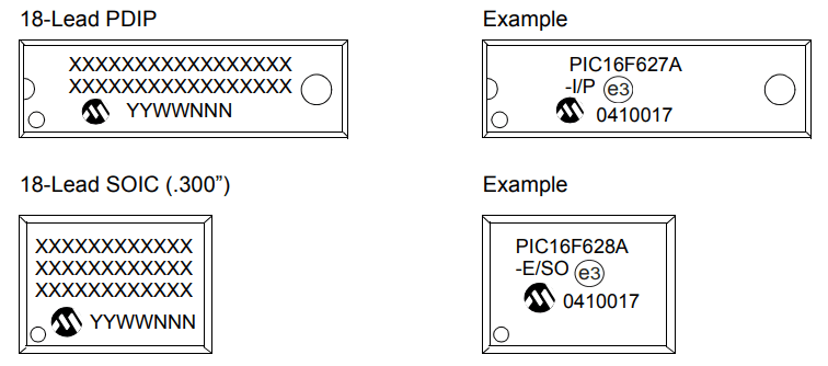
| Package Types | 18-Lead PDIP, 18-Lead SOIC |
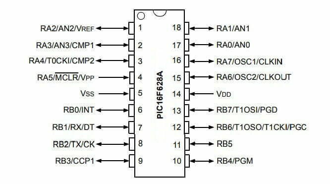
PIC16F628A Bring-Up, Configuration, and ICSP Checks
The PIC16F628A is an 8-bit controller whose startup behavior is strongly shaped by configuration bits, oscillator choice, MCLR wiring, low-voltage programming selection, and the default state of multiplexed peripherals. A pin may not behave as digital I/O until comparator or alternate functions are configured. Before application code, verify supply decoupling, reset timing, clock activity, and a minimal output. Preserve RB6, RB7, MCLR/VPP, power, and ground access for ICSP.
- Configuration word: Set oscillator, watchdog, power-up timer, brownout, MCLR, code protection, and LVP deliberately.
- Comparator ownership: Disable or configure the analog comparators before expecting their shared pins to read as digital inputs.
- Clock verification: Confirm the selected internal or external clock and measure instruction timing with a simple toggling output.
- ICSP loading: Prevent attached circuits from fighting programming clock, data, or VPP during in-circuit programming.
- Voltage limits: Use the data-sheet supply range and pin current limits; never apply programming voltage to an unprotected signal.
Application
The PIC16F628A series fits in applications ranging from battery chargers to low power remote sensors. The small footprint packages makes this microcontroller series ideal for all applications with space limitations.