PCB Repair Service
About Printed Circuit Board Repair
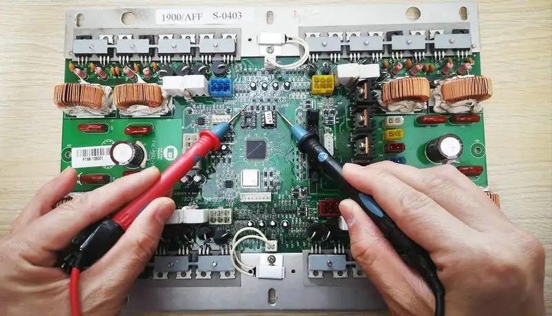
Repairing damaged PCBs is a specialist affair, requiring a vast level of expertise and experience to ensure that your board is repaired and tested to the highest standards. This can also be an extremely time-consuming job, particularly for complex or single-layer boards with a high density of copper tracks and components, and where track damage or component failure has left no traces for component identification.
Our PCB Repair Services
We offer a wide range of PCB repair services including component rework, solder mask repair, de-solder and relayout of boards, fitting switches and sockets, fitting battery replacements and making changes to fix an existing design flaw. This is all done using our in-house hot air oven, specialist soldering and fluxing equipment, PCB test equipment, automated UV inspection systems and pick & place machine. Our specialist equipment ensures that whilst we are fast to respond we are also able to deliver safe and professional reworks that ensure your boards meet all local and international standards. Below are common pcb rework and repair:
- Repair of ball grid array (bga rework)
- Repair of surface mount
- Repair or installation of through-hole components
- Repair of surface mount pads
- Repairing traces
- Re-laminating
- Circuit modification and repair
How to Repair Circuit Board?
If you have some damaged pcbs that needs repair, don’t despair! With our professional repair tools and technology, we can help to repair your circuit board and make it running back to normal! Here’re the full repair process in 8 steps:

1. Prepare PCB repair kit
To repair the damaged parts of printed circuit boards, you will need a few tools and materials: sharp or flat-blade screwdriver, copper foil tape, welding gun, heat gun, scissors or craft knife, fountain pen, cotton swabs and alcohol wipes, tweezers, paper clip.

2. Remove damaged pads or components
If you find that a component on your PCB is not working properly, you can follow these simple steps to remove and replace the component:
• Use a heat gun to heat the faulty element for a few seconds.
• Remove the element with tweezers. If it doesn't come off easily, heat it for a few more seconds.
• If the PCB pad is thermally damaged, carefully remove it with a sharp knife.
3. Clean the copper wire and remove the solder
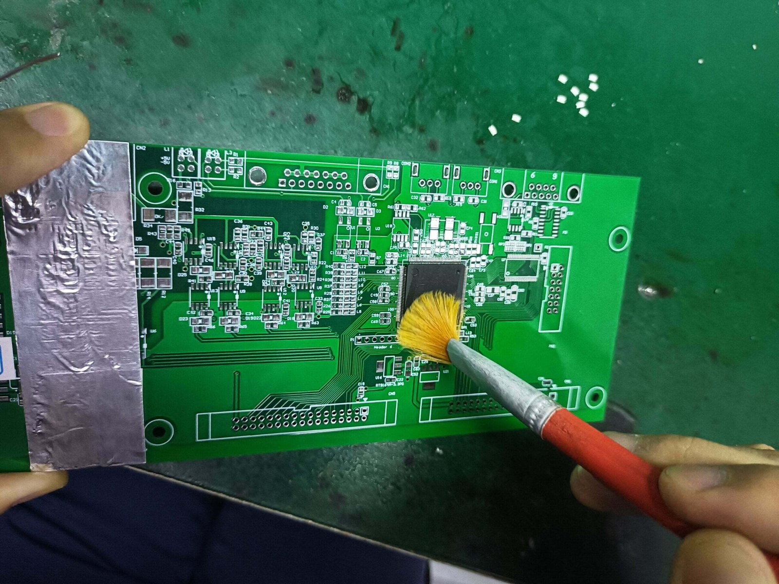
After removing the damaged pad, continue to use a sharp knife to remove the solder on it. If using a knife is inconvenient for this more delicate operation, you can also use a pointed screwdriver or fine-grit sandpaper.No matter which tool you use, you should end up with the copper wire fully exposed, with no solder remaining, and looking clean and shiny.
4. Apply copper foil tape to the copper wire
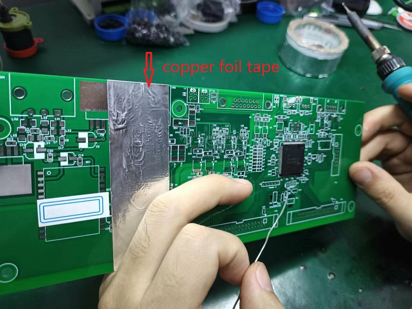
Once the damaged copper wire has been removed and the area cleaned, the copper foil tape can be applied.The copper foil tape should overlap the existing copper lines and cover the existing vias and part of the surrounding area.
5. Solder the Joints
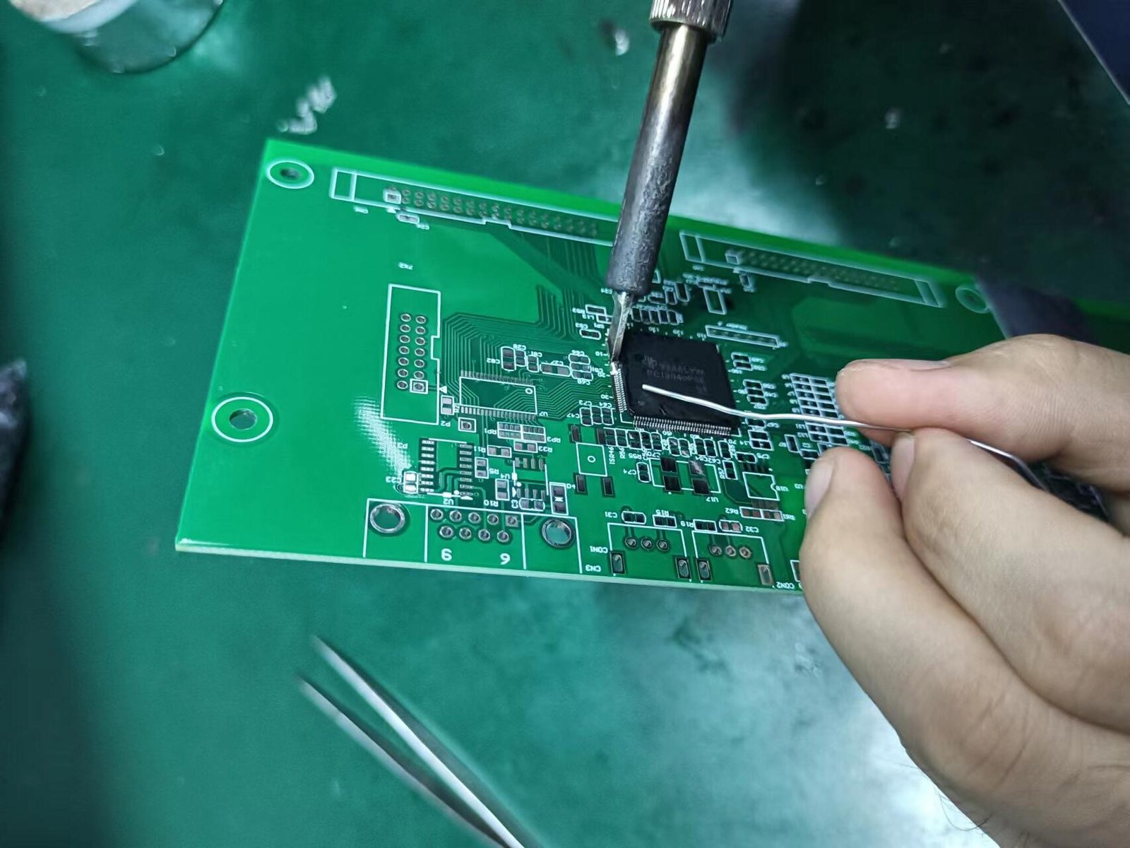
At this point, it is necessary to carefully solder the joints where the new copper foil tape is connected to the repaired PCB copper wires. Here are some relevant tips and warnings:
• Copper foil tape melts quickly at soldering temperatures, so make sure you can do this in one go.
• Heat as little as possible, and must be done carefully and quickly to reduce the amount of heat applied.
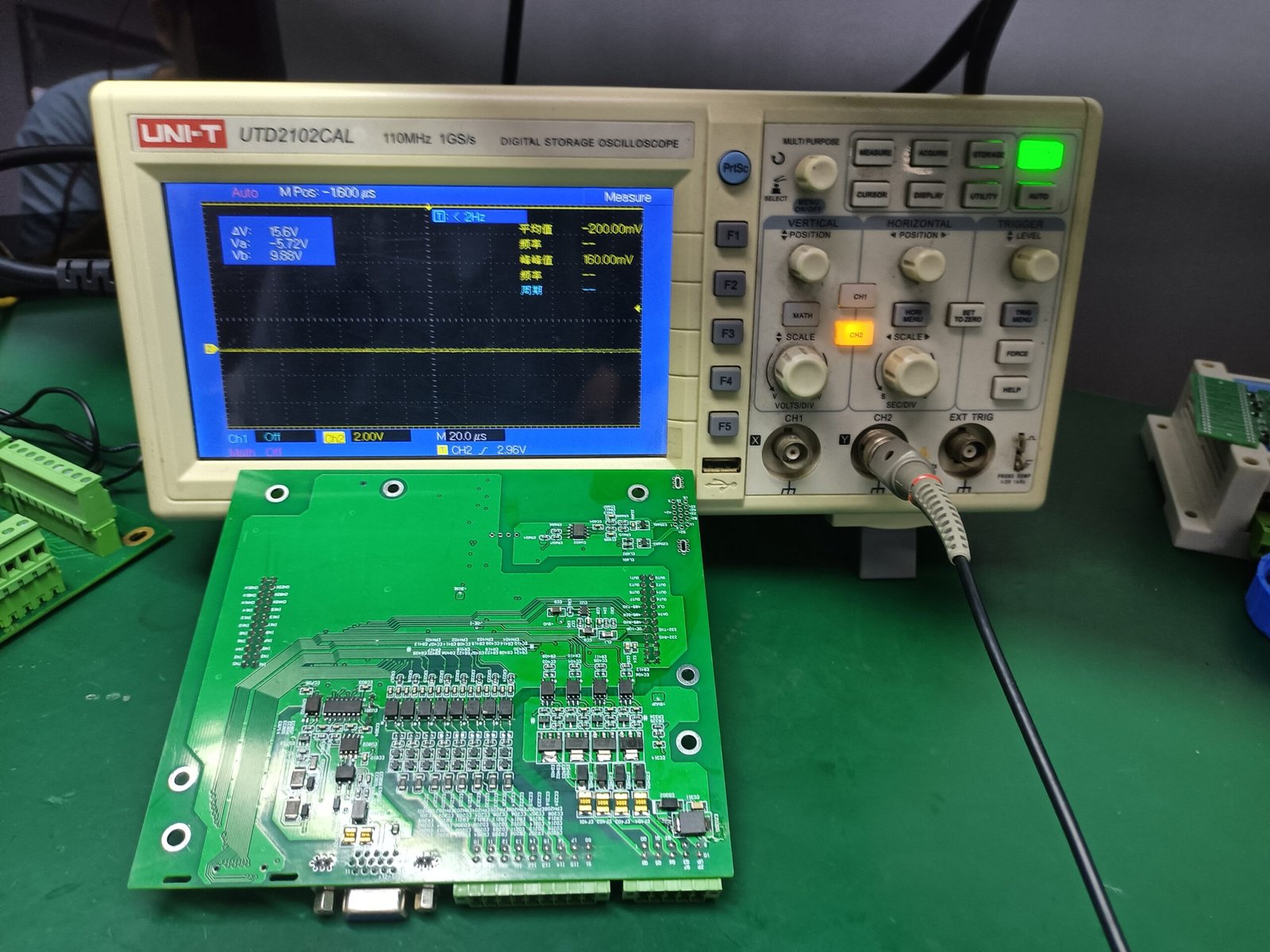
6. Restore PCB Vias
Find a hard tool with a round tip, such as a pen or other simple tool. Press on the area you just finished soldering and rub hard to make sure the copper foil tape is firmly attached to the entire pad area. After the area was heated, the tape was still sticky.Use this trick to locate the vias, then use a paper clip or other similar tool to make the holes.
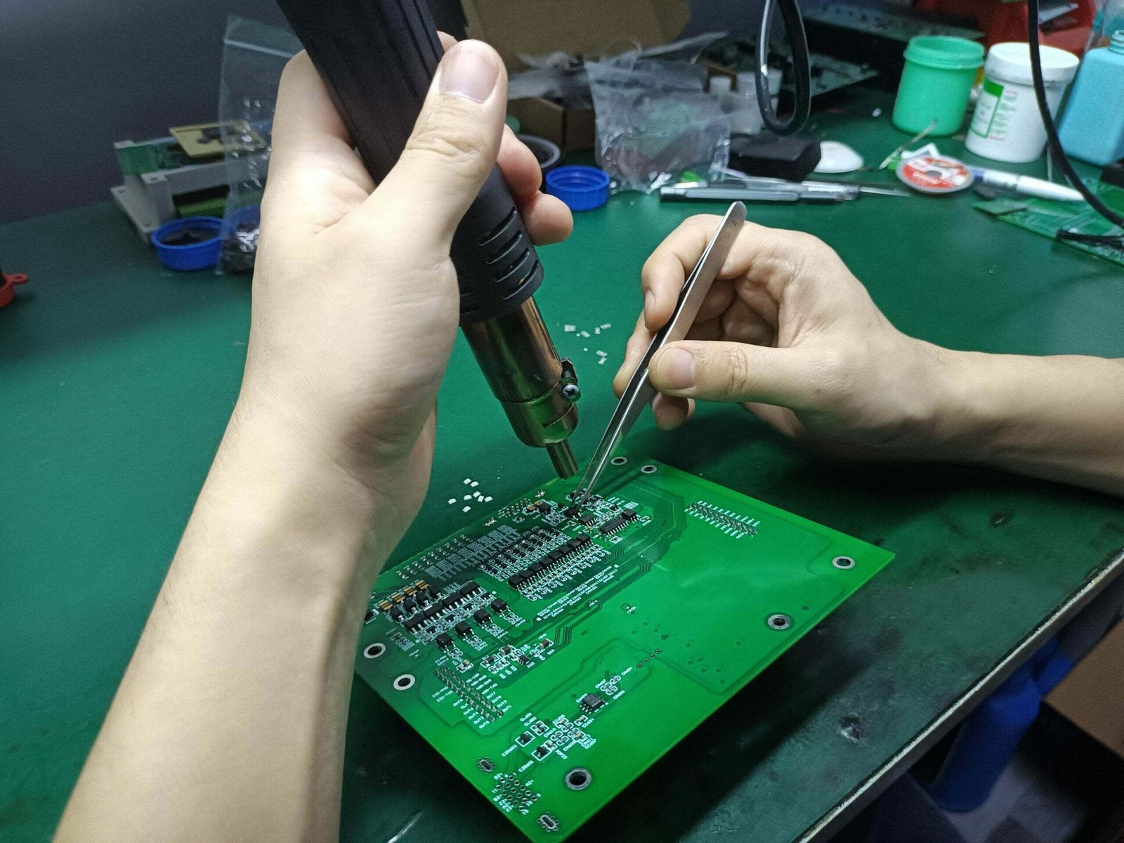
7. Place Components and Solder
After completing the above steps, the PCB is repaired and ready to accept the new components selected.The next process of soldering components is familiar to everyone. As before, heat as little as possible. The new solder joints between the newly applied copper foil tape/pads and the copper wire may not be quite secure yet.
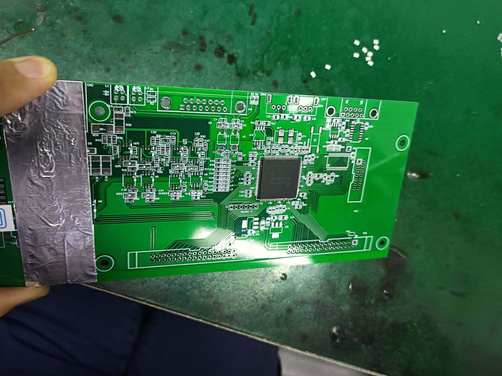
8. Cut off excess tape in repair area
Using scissors or a craft knife, carefully cut the copper foil tape to size to complete the repair. It's important to note that just-repaired solder joints may restore functionality to the PCB, but the pads, copper wires, and connectors will never be as strong as the previous board.
PCB Repair Price
Prices for PCB repair can vary depending on the severity of the damage and the type of board that needs to be repaired. The average pcb repair cost is around $150. However, the price can range anywhere from $100 to $500 depending on the severity of the damage. If the damage is extensive, it may even cost more than $500 to repair. Pcb repairs are not typically covered by insurance, so it is important to be aware of the potential costs before having any repairs done.
Absolutely Reasonable Price & Fast Quote
Business Flow

Submit Demand
Submit your exact details of pcb repairing on the form, and upload your pcb files. Then we'll reply to you within 24 hours.

Confirm The Repair Details
Our expert will contact you for the details of pcb repair, like repair area and cost. Then we will reply to you with a formal quotation.
Send the damaged PCBs
Once the PCB repair service is confirmed and we receive the payment. You can send your PCBs to us.

Repairing & Shipping
At last, we start to repair your damaged pcbs, and shipped back to you by air or ocean. You'll reveive them about 7~15 days.
Why Choose Us?
Quick PCB Repair Service
Our Quick PCB Repair Service is the perfect solution for you. We offer a wide range of services to meet your needs, and our experienced team of technicians will work quickly and efficiently to get your board repaired and back to you as soon as possible.
High Quality Guaranted
We have high quality electronic components to assurance standard pcb repair process, and advanced manufacturing as well as testing equipment to provide excellent quality assurance.
Reduce Cost for You
Reduce the cost of customers, balance customer needs and manufacturing constraints, optimize the PCB copy board design scheme – directly save your time and money.
Explore More Knowledges

Keil μVision5: Tutorial for Beginners
What is Keil μVision5? Keil μVision5 is an embedded software development tool used for writing, debugging, and testing applications for embedded systems. It provides various

Keil μVision5: Tutorial for Beginners
What is Keil μVision5? Keil μVision5 is an embedded software development tool used for writing, debugging, and testing applications for embedded systems. It provides various

IC Unlock or Decrypt: What is, and How to do?
What is IC Unlock? IC unlock is aslo called IC decrypt, IC attack or IC crack. An IC (integrated circuit) is usually encrypted when it
