Restauración de esquemas y Gerber
Acceso y copia de seguridad de código MCU/CPLD
Replicación exacta de hardware 1:1
Soluciones inalámbricas BLE y BT clásica
Gestión térmica y PID de precisión
Control de unidad de conducción de motores de alta eficiencia
Comunicación industrial RS485/RTU
Firmware y HW STM32/ESP32 personalizados
Optimización para costo y rendimiento
Diseño de PCB de múltiples capas de alta velocidad
Muestras de entrega rápida para verificación
PCBA y obtención de componentes llave en mano
Experiencia en tecnología de montaje superficial
Identificación de las causas raíz de las fallas de los chips
Restauración de la placa a nivel de componentes
Pruebas de estrés térmico y eléctrico
Descubra la ingeniería detrás de los microprobes de precisión
Almacenamiento de energía y cálculo reactivo
Procesamiento de señales y herramientas de frecuencia
Leyes básicas de circuitos y serie-paralelo
Herramientas de referencia electrónica general
Calcule el ancho de traza de PCB en función del aumento de temperatura, la corriente y el espesor del cobre (IPC-2152).
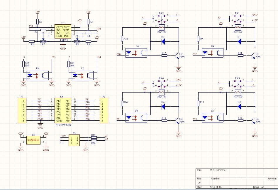
This project involves a H-Bridge motor driver circuit, designed to control the speed and direction of a DC motor. The circuit utilizes a PWM (Pulse Width Modulation) signal to regulate the motor’s current and torque. The H-Bridge configuration allows for the creation of a closed-loop control system, enabling precise motor speed adjustments.
«,»1″:»H-Bridge Motor Driver Circuit Schematic»,»2″:»Project Overview»,»3″:»The circuit’s primary function is to provide a stable and responsive motor control system. It incorporates a PWM signal generator to modulate the motor’s voltage, allowing for precise speed and torque control.
«,»4″:»Motor Control Algorithm»,»5″:»A feedback loop is implemented to monitor the motor’s position and adjust the PWM signal accordingly. The motor’s position is determined by a sensor, typically a potentiometer, which provides a reference point. The PWM signal is then generated to drive the motor, effectively controlling its speed and direction.
«,»6″:»H-Bridge Motor Driver Circuit Design»,»7″:»Project OverviewIn this project, the circuit acts as a heating system for the PCB to maintain its temperature above the device’s minimum operational limit, particularly in low temperatures. Since precise temperature control is not required, the design uses a voltage divider composed of a resistor and an NTC thermistor to control a MOSFET or transistor. When the temperature drops below a set threshold, the voltage across the divider increases, turning on the heating circuit. As the temperature rises again, the voltage decreases, turning the circuit off.
We use a common SOT-23 package for the transistor and MOSFET. MOSFETs generally support higher conduction currents compared to transistors in the same package, so we selected the LN2302BLT1G MOSFET from LRC. The NTC thermistor chosen is the commonly used NCP15WF104F03RC. For heating elements, we use a 1210-package 10Ω resistor, controlling the total power to 2.5W.
In the schematic, the signal THERM_PCB is an analog input fed to the microcontroller’s ADC for PCB temperature monitoring. The HEATER_EN signal connects to a microcontroller IO pin. The pin is set to high impedance, but if the heating circuit malfunctions, the IO can pull the signal high to force the MOSFET off as a safety measure.
The H-Bridge motor driver circuit using the L293D is simple, requiring only four external diodes. The circuit drives two motors with two input signals controlling two separate motors. Motor 1 input signals are applied to pins 1A and 2A, while outputs are from pins 1Y and 2Y. Similarly, Motor 2 input signals are applied to pins 3A and 4A, with outputs from pins 3Y and 4Y. Diodes D1–D4 protect the motors from reverse voltage spikes.
The L293D is a high-current half-H driver capable of supplying up to 600mA of bidirectional drive current. It can control inductive loads, such as motors, relays, solenoids, and bipolar stepper motors.
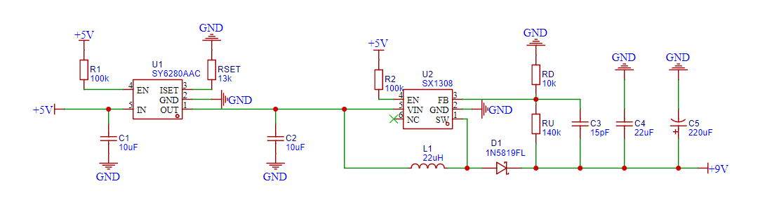
A switching power supply, also known as a switch-mode power supply (SMPS), is a high-frequency power conversion device. Its purpose is to convert voltage from one level to another based on the needs of the end-user, using different circuit architectures.
The circuit is designed to oscillate between 30kHz and 45kHz, regulated by adjusting capacitor C3 and resistor R5. The output voltage needs to remain stable, with a maximum output current of 500mA. The power supply delivers 8W of effective power with an efficiency of 87%.
Проектирование схемы ПЛИБ является критическим шагом в любом электронном проекте. Используя стандартные руководства и современные инструменты проектирования, дизайнеры могут создавать надежные и эффективные схемы. Приведенные примеры иллюстрируют разнообразие и применение различных типов схем, от простых схем нагрева до двигателей и источников питания.

I am Aidan Taylor and I have over 10 years of experience in the field of PCB Reverse Engineering, PCB design and IC Unlock.