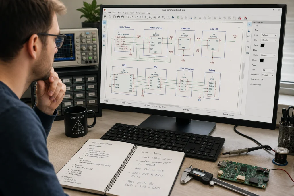
Se vuoi creare un Design Kica Dal testo, la parte difficile è raramente disegnare fili. La parte difficile sta trasformando un requisito libero in qualcosa che Kicad può controllare, un altro ingegnere può rivedere e Layout può fidarsi. Un messaggio di testo che dice “Crea una scheda sensore ESP32” non è sufficiente. Hai bisogno di simboli espliciti, nomi di rete, ipotesi di potere, designatori di riferimento e regole per ciò che deve accadere quando la bozza è in conflitto con il foglio dati.
Ecco perché i flussi di lavoro KICAD basati su testo sono utili per l’ambito e l’acquisizione schematica di primo passaggio, ma rischioso quando i team li trattano come un sostituto con un clic per il giudizio ingegneristico. L’approccio più sicuro consiste nell’usare il testo per definire la struttura, lasciare che lo strumento costruisca una bozza e quindi verificare ogni parte di quella bozza come se provenisse da un ingegnere junior il primo giorno.
Cosa dovrebbe significare in pratica “creare un disegno Kicad dal testo”
Per un vero flusso di lavoro PCB, il design basato su testo dovrebbe produrre più di uno screenshot piuttosto schematico. dovrebbe risultare in un progetto KICAD modificabile con un valido .kicad_sch Gerarchia, scelte di simboli comprensibili, etichette di rete leggibili e contesto di progetto sufficiente che qualcun altro può continuare a lavorare senza invertire le ipotesi del generatore.
La documentazione di Kicad è importante qui. Uno schema è organizzato come uno o più fogli, con disegni gerarchici costruiti da un foglio radice e fogli subordinati. Questa struttura è importante perché molti esperimenti prompt-to-schematiche falliscono quando possono nominare parti e fili ma non possono mantenere coerenti i segnali della gerarchia, del riutilizzo del foglio e dell’interfaccia per l’intero progetto.
In altre parole, un risultato utilizzabile non è “l’IA ha disegnato un convertitore di dollari”. Un risultato utilizzabile è “Il progetto generato ha il simbolo del regolatore giusto, il pin di abilitazione non è fluttuante, le reti di feedback sono chiamate chiaramente, le parti di disaccoppiamento sono presenti e la gerarchia ha senso quando il tabellone cresce in revisione B”.
Inizia con una specifica di testo che Kicad può sopravvivere
Se il testo sorgente è vago, l’output sarà vago in una forma più pericolosa. Prima di generare qualsiasi cosa, converti il prompt in un brief di ingegneria strutturato.
Definire le parti per funzione, non per il solo nome di marketing
Scrivi il controller, i dispositivi di interfaccia, i regolatori, gli oscillatori, i connettori e le parti di protezione in termini funzionali. “Scheda ESP32-C6 alimentata da USB-C con guida da 3,3 V, intestazione di debug UART, ESD su USB D+/D- e pulsanti di ripristino/avvio” è molto più forte di “Scheda di sviluppo ESP32”. Il secondo prompt lascia troppo spazio per il ponte USB sbagliato, l’albero di alimentazione sbagliato o un simbolo che non corrisponde al pacchetto che puoi effettivamente reperire.
Indicare esplicitamente il percorso di alimentazione e gli stati predefiniti
Gli schemi generati dal testo sembrano comunemente accettabili fino a quando non si ispeziona l’inserimento dell’alimentazione, si abilitano i pin, i pull-up e le ipotesi di non connessione. Dì dove entra il potere, quali binari devono esistere, quali pin richiedono resistori di trazione e cosa dovrebbe accadere all’accensione. È qui che molte bozze generate falliscono ERC in seguito, o peggio, passano ERC pur creando una scheda che si avvia in modo inaffidabile.
Descrivi reti, interfacce e vincoli denominati
Se l’obiettivo è un design KICAD riutilizzabile, il prompt dovrebbe nominare gli autobus e le reti critiche come farebbe il team umano. Clear Net Naming riduce i tempi di revisione e impedisce al generatore di creare un pasticcio di etichette generiche che devono quindi essere rielaborate a mano. Se sai già che hai bisogno di reti distinte per vbus, 3v3, IT, Stivale, USB_D_P, e USB_D_N, dichiarali in anticipo.
Questa è anche la fase in cui dovresti decidere quanta gerarchia merita il progetto. Un minuscolo breakout board può vivere su un foglio. Una scheda di controllo a segnali misti con sezioni di alimentazione, radio e sensori di solito non dovrebbe.
Perché i flussi di lavoro da testo a kicad si interrompono ancora
L’attuale generazione di strumenti è molto migliore per creare una bozza schematica che per garantire l’intenzione di progettazione. Ricerche recenti come Schgen e PcbSchemagen mostrano chiari progressi nella conversione delle richieste di linguaggio naturale in rappresentazioni schematiche modificabili, ma quei sistemi enfatizzano ancora il controllo e la riparazione dei vincoli perché il linguaggio semplice da solo non è abbastanza affidabile.
Ciò corrisponde a ciò che gli utenti di Kicad hanno detto nella comunità per un po’. Discussioni nei forum sulla generazione e la manipolazione schematica guidata dalla rete continuano a tornare agli stessi punti di attrito: creare simboli è più facile che preservare la connettività corretta, generare un file è più facile che generare un progetto gestibile e il ciclo di verifica conta più del passaggio iniziale di sintesi.
Tre modalità di errore appaiono ripetutamente nella pratica:
Innanzitutto, la mancata corrispondenza del pacchetto di simboli. Un generatore di testo può scegliere un simbolo logico che sembra a posto sul foglio ma non corrisponde alla famiglia di impronte, ai pin nascosti o alla convenzione di denominazione dei pin utilizzata dalla libreria approvata. Questo diventa un problema di distinta base e di layout in seguito, non solo un problema schematico.
In secondo luogo, la semantica della connettività debole. I cavi possono esistere, ma i pin sbagliati sono legati insieme, vengono utilizzati no-connect dove sono necessari componenti di trazione o le reti di alimentazione vengono unite in modo troppo aggressivo. Ciò è particolarmente rischioso su regolatori, amplificatori operazionali, bridge USB e moduli radio in cui una parte mancante di polarizzazione può trasformare un design “di bell’aspetto” in una scacchiera.
Terzo, intento ingegneristico illeggibile. L’output può passare un controllo di sintassi ristretto ma essere comunque infelice da rivedere perché i blocchi non sono raggruppati in modo logico, le etichette sono incoerenti e la gerarchia è assente. Quel costo si manifesta durante la revisione ecologica e il debug di DFM, quando qualcuno deve scoprire perché lo strumento ha fatto determinate scelte invece di seguire semplicemente una narrativa di design pulito.
Un flusso di lavoro più sicuro per la generazione di schemi KICAD dal testo
Il flusso di lavoro più affidabile non è Prompt, Genera e Invia al layout. È tempestivo, vincolare, generare, ispezionare, riparare e solo allora continuare.
Inizia con un brief di testo che includa blocchi funzionali, binari richiesti, interfacce protette, aspettative sui pin del connettore e regole note “non devono violare”. generare la prima bozza schematica da quel brief. Quindi esaminalo rispetto ai fogli dati e agli standard interni della tua libreria prima ancora di pensare al posizionamento.
In questa fase di revisione, controlla la scelta del simbolo, i designatori di riferimento, i perni di alimentazione dell’unità, i valori dei resistori predefiniti, la logica pull-up e pull-down, l’intento di disaccoppiamento del posizionamento e se i nomi di rete avranno ancora senso una volta che il design diventa una scheda. Se la bozza utilizza fogli gerarchici, verificare che i pin del foglio riflettano i limiti del sottosistema reale anziché il raggruppamento arbitrario.
Successivamente, esegui ERC e tratta ogni avviso come un elemento di revisione del design, non come un fastidio estetico. Uno schema generato che richiede cinque minuti di pulizia ERC spesso nasconde un problema più profondo nel prompt originale o nella mappatura della libreria. Se ignori quel segnale, la fase di layout lo eredita come rielaborazione.
Cosa verificare prima che il progetto lasci l’acquisizione schematica
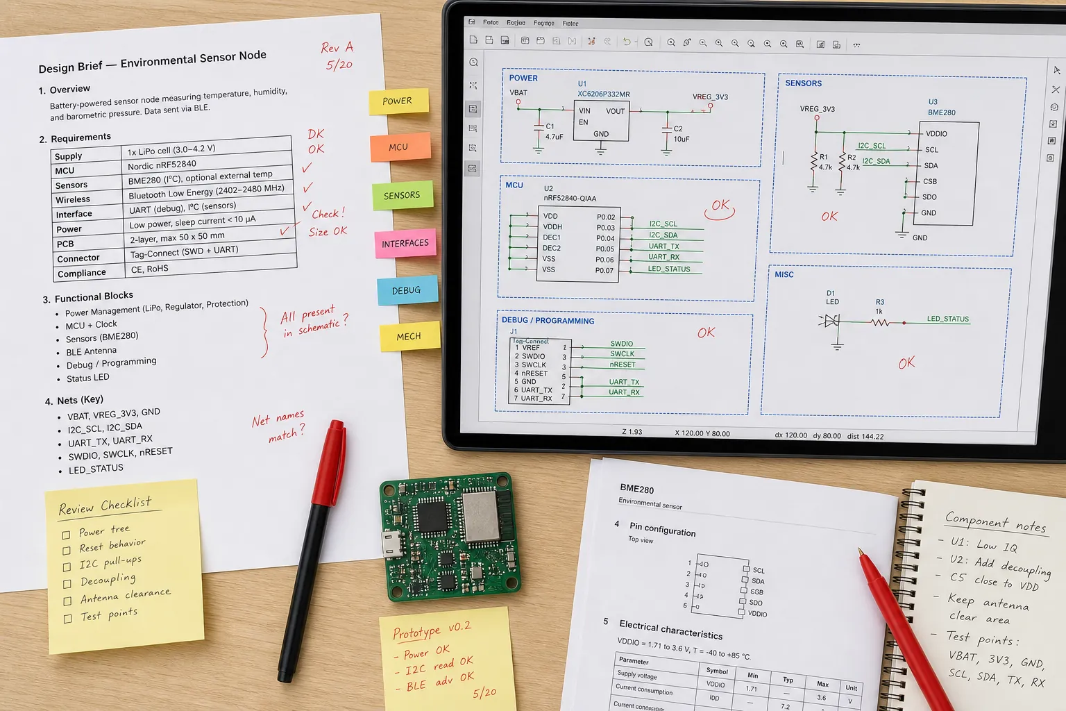
Non fermarti a “Il file si apre in KiCad”. Una revisione orientata alla produzione dovrebbe rispondere se lo schema generato è producibile, testabile e riparabile.
Per la producibilità, confermare che le ipotesi del pacchetto corrispondono alla realtà di approvvigionamento. Uno strumento di testo può selezionare un regolatore generico o simboli di connettore senza rispettare il pacchetto che puoi effettivamente acquistare nel tuo canale approvato. Ciò diventa un rischio di impronta e assemblaggio, in particolare per parti di altezza fine, pacchetti insoliti di pad a vista o componenti con più pinout del fornitore con nomi quasi identici.
Per la verificabilità, cerca la strategia di accesso mancante. Gli schemi generati spesso ignorano il modo in cui la scheda verrà programmata, resettata, misurata o isolata durante il richiamo. Se il progetto include un microcontrollore, definire l’intestazione di debug, i cinghie della modalità di avvio, i test pad e i punti di interruzione della misurazione della corrente prima che il progetto vada avanti.
Per la funzionalità, verificare che la denominazione e il raggruppamento della rete saranno ancora comprensibili dopo sei mesi. Le etichette chiare contano qui. Se hai bisogno di un aggiornamento su come l’ambito di denominazione influisce sul riutilizzo e sul debug, la Guida ReversePCB esistente su Making Etichette in KICAD senza confondere reti locali, globali e gerarchiche è direttamente rilevante.
Dovresti anche rivedere l’output nello stesso modo in cui rivedresti uno schema creato dall’uomo contro più ampio PCB Migliori pratiche di progettazione schematica. Il generatore può accelerare l’acquisizione del primo passaggio, ma non rimuove la necessità di partizionamento leggibile, annotazione ragionevole e denominazione deliberata del segnale.
Quando vale la pena utilizzare il design KiCad basato sul testo
Questo flusso di lavoro è più forte quando il problema è strutturato ma ripetitivo: interruzioni dell’interfaccia, semplici schede di supporto del controller, dispositivi di prova, rimappa dei connettori, schede dei sensori o varianti interne in cui l’architettura è già intesa. In questi casi, il testo può codificare regole ripetibili e ridurre il tempo trascorso a ridisegnare i circuiti standard.
È molto più debole per sezioni analogiche ambigue, vincoli ad alta velocità, protezione a tensione mista, corrispondenza RF o progetti che dipendono fortemente dai circuiti di riferimento specifici del fornitore. In questi casi, il generatore può comunque aiutare a assemblare una bozza, ma il valore ingegneristico deriva dalla velocità con cui espone le ipotesi mancanti, non dalla velocità con cui finisce l’intero progetto.
Una buona regola è semplice: utilizzare la generazione basata su testo per accelerare l’acquisizione strutturata, non per esternalizzare la responsabilità. Più un progetto dipende da avvertimenti del foglio dati nascosti, comportamento termico, controllo EMI o eccezioni a livello di pacchetto, meno dovresti fidarti di un flusso di lavoro solo prompt.
Conclusione
Se vuoi creare un disegno Kicad dal testo, i migliori risultati derivano dal trattare il testo come un livello di specifiche, non una scorciatoia sulla revisione ingegneristica. Scrivi il prompt come un documento di trasferimento, forza la bozza per esporre chiaramente i simboli e le reti denominate e esaminala con ERC, schede tecniche, vincoli di approvvigionamento e esigenze di debug prima dell’inizio del layout.
Questo approccio non rimuove il lavoro schematico. Rimuove il lavoro evitabile a pagina bianca mantenendo le decisioni che appartengono ancora all’ingegnere. Per i progetti hardware in stile ReversePCB, questa è la differenza tra una demo intelligente e uno schema che puoi effettivamente rilasciare.
FAQ
KICAD può generare nativamente uno schema completo da un prompt in linguaggio semplice?
La stessa KICAD è un ambiente di progettazione schematica e PCB, non un generatore di prompt-to-schematico nativo. In pratica, i flussi di lavoro basati su testo si basano su script esterni, strumenti di ricerca o livelli di generazione di codice che emettono file di progetto, simboli o netlist compatibili con KICAD, che necessitano ancora di una revisione ingegneristica all’interno di KICAD.
Cosa dovrebbe includere un prompt di testo prima di generare un design KiCad?
Includere i blocchi funzionali, le interfacce esatte, i binari di alimentazione, i resistori di trazione richiesti, le aspettative dei connettori, le parti di protezione, le convenzioni di denominazione nette e tutte le regole imperdibili dal foglio dati. Più il prompt è esplicito, meno pulizia avrà bisogno lo schema generato.
Qual è il rischio più grande quando si crea un design Kicad dal testo?
Il rischio più grande è fidarsi di una bozza che sembra ragionevole ma codifica l’intento elettrico sbagliato. I problemi comuni includono la mancata corrispondenza del pacchetto di simboli, le parti mancanti o le parti di protezione, l’etichettatura della rete debole e gli errori di connettività che si manifestano solo quando iniziano i lavori ERC, layout, test o sourcing.
Quando è più utile la generazione schematica basata sul testo?
È molto utile per progetti strutturati e ripetibili come semplici schede portanti MCU, sblocchi, dispositivi di test e varianti di interfaccia in cui l’architettura è già intesa. È meno affidabile per ambigui progetti analogici, RF, a tensione mista o ad alta velocità che dipendono fortemente dall’interpretazione dettagliata della scheda tecnica.