Спросите инженера «Что такое SMT», и вы обычно слышите «Технологии поверхностного крепления». Это правильно. Но если вы остановитесь на аббревиатуре, вы пропустите то, что СМТ на самом деле означает За то, как печатная плата проектируется, строится, тестируется и оплачивается. В этой статье объясняется Определение СМТ В терминах, которые важны для тех, кто разрабатывает, заказы или устраняет неполадки в собранных печатных платах.
Простое определение SMT
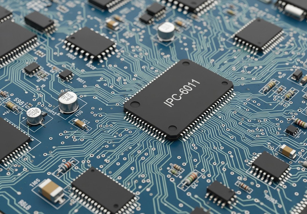
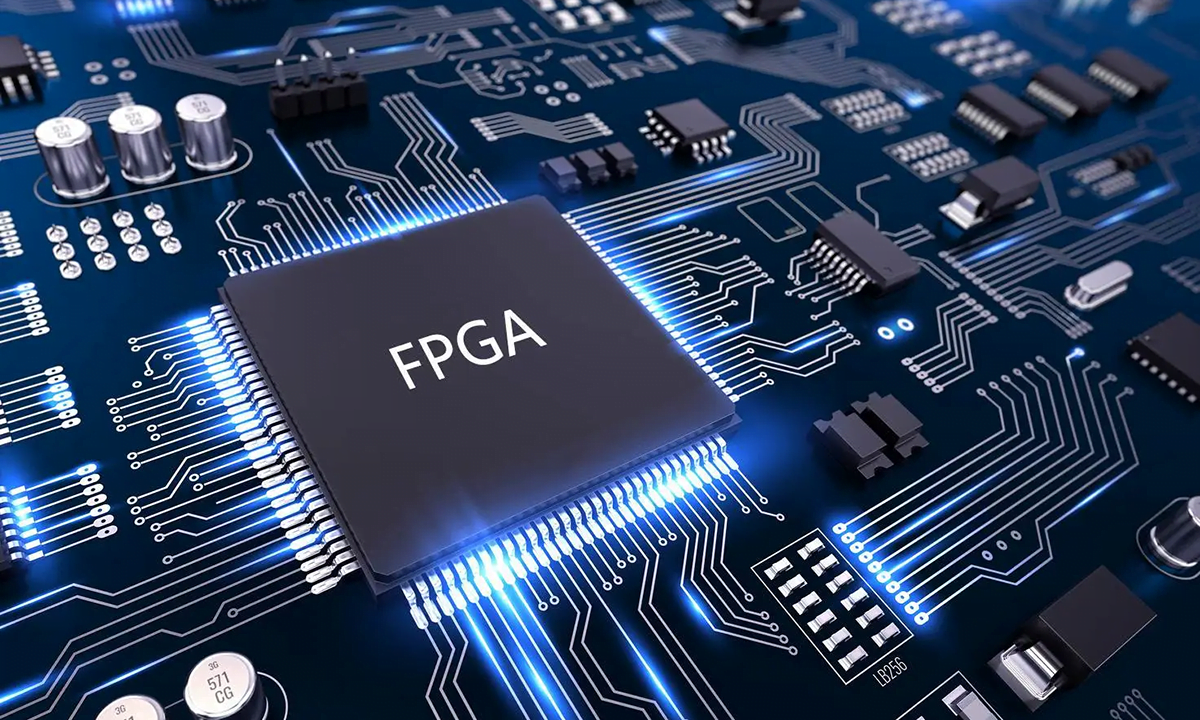
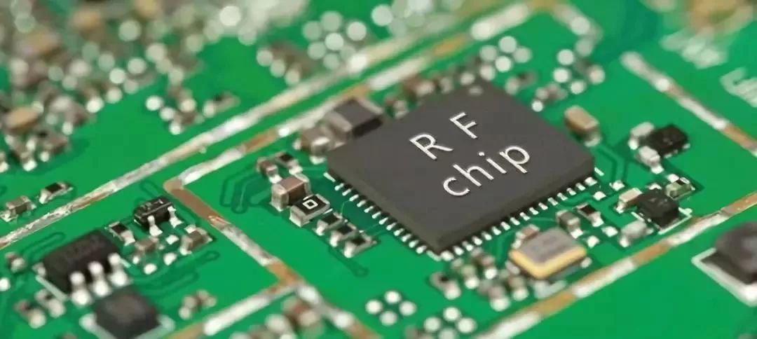
смт (Технология поверхностного монтажа) — это метод сборки печатных плат, при котором компоненты монтируются непосредственно на поверхность печатной платы без проводов, проходящих через отверстия. Это заменило сквозную технологию (THT) в качестве доминирующего метода производства, начинающегося в 1980-х годах, и в настоящее время приходится подавляющее большинство коммерческой сборки печатных плат.
Ключевое различие: в сборке сквозных отверстий компоненты GO через Просверливаем отверстия и припаяны на противоположную сторону. В SMT компоненты SITE наверху прокладок, напечатанных с помощью паяльной пасты и припаяны на месте во время оплавления. Без отверстий, без обрезки свинца и значительно более высокой плотности компонентов.
Какие «SMT» меняет в дизайне печатной платы
Если вы выросли на сквозном прототипировании, переход на SMT означает переосмысление нескольких дизайнерских привычек:
- Маршрутизация трасс становится более жесткой. SMD-прокладки меньше и ближе друг к другу. Вы можете поместить развязывающий конденсатор в пределах миллиметра от IC питания IC, что улучшает целостность сигнала так, как сквозные отверстия расположены редко.
- Обе стороны становятся пригодными для использования. Компоненты SMT могут заполнять как верхнюю, так и нижнюю часть платы. Это удваивает эффективную площадь без увеличения контура печатной платы, что имеет большое значение для компактных потребительских товаров.
- VIA становятся инструментами маршрутизации, а не якорями компонентов. Поскольку компоненты не нуждаются в нанесении сквозных отверстий, VIA высвобождаются исключительно для переходов слоев и терморегулирования.
- Тепловые сдвиги. Компоненты SMD рассеивают тепло в медные плоскости через свои прокладки, а не через ведущие провода. Правильная заливка меди под силовой SMD-части больше для охлаждения, чем сквозная зажим радиатора.
Если вы уже опубликовали дизайн, ориентированный на SMT, и хотите перенести его в производство без перепроектирования всей спецификации, Служба сборки обратного печатания Обрабатывает доски смешанной технологии, где сосуществуют компоненты SMT и сквозные отверстия.
SMT против сквозного отверстия: Реальность сборочного этажа
The Определение СМТ Важнее всего на конвейере. Вот что меняется, когда конструкция переключается со сквозного отверстия на SMT:
| Аспект | сквозная дыра | Смт |
|---|---|---|
| Размещение компонентов | Ручные или волновые припоя | Автоматизированный выбор и размещение на тысячах CPH |
| Пайка | Волновая или ручная пайка | Перезарядка печь с контролируемым термопрофилем |
| Совет по недвижимости | Потребляет обе стороны со свинцовыми отверстиями | Компоненты сидят на поверхности, обе стороны могут быть использованы |
| Минимальный размер компонента | ~0805 эквивалент | до 01005 (0,4 х 0,2 мм) |
| Сложность переделки | легко с паяльником | Требуется горячий воздух, подогрев или специальная станция ремонта |
| Механическая прочность | Сильнее (выводить сквозь отверстие) | Слабее против стрижки, полагается на сцепление с прокладками |
Для большинства производственных работ более нескольких десятков юнитов SMT выигрывает по скорости, постоянству и стоимости за единицу. Компромисс заключается в авангарде: трафареты, программирование «выбор-установка» и профилирование перепрошивки — все это происходит до того, как отправятся первые борта.
Компоненты SMD: что монтируется
Компоненты, используемые в Технология поверхностного монтажа называются SMDS — устройствами для поверхностного монтажа. Общие типы пакетов SMD включают в себя:
- Пассивные микросхемы (резисторы, конденсаторы, индукторы): такие стандарты, как 0402, 0603, 0805. Номер указан в сотых долях дюйма — 0603 0,06″ x 0,03″.
- SOIC, SSOP, TSSOP: ведущие чайные крылья ИКС, рабочие лошадки аналоговых и смешанных сигнальных схем.
- QFP, LQFP, TQFP: квадратные микросхемы с отведениями с четырех сторон, распространенные на микроконтроллерах до ~ 200 контактов.
- QFN, DFN: бессвинцовые пакеты с открытыми термопрокладками внизу. Труднее припаять, превосходные тепловые характеристики.
- BGA: Массивы шаровых сеток прячут шарики для пайки под упаковкой. Невозможно визуально осмотреть после оплавления без рентгеновского излучения.
- 0201, 01005: Ультраминиатюрные пассивные устройства, используемые в телефонах и носимых устройствах. Ручная пайка нереалистична.
Выбор правильного пакета — это решение как электрическое, так и электрическое. Если ваш контрактный производитель не может надежно разместить детали 0201, не указывайте их.
Процесс сборки SMT в четыре этапа
понимание Технология поверхностного монтажа Рабочий процесс помогает вам писать лучшие правила DFM:
- Печать паяльной пасты. Трафарет из нержавеющей стали выравнивается по голой печатной плате. Паяльная паста по нему выдавливается, нанося пасту только на компонентные прокладки. Толщина трафарета, конструкция диафрагмы и реология пасты контролируют объем отложения.
- Выбирайте. Высокоскоростная машина собирает SMD из катушек или лотков, используя вакуумные форсунки, и помещает их на наклеенные прокладки. Точность размещения обычно лучше, чем 50 мкм для современных машин.
- Пайка оплавления. Населенная плата проходит через печь с контролируемым нагревом. Термальный профиль нарастает, впитывается для активации флюса, качается выше ликвидуса (~217°C для бессвинцового припоя SAC305), затем охлаждается с контролируемой скоростью. Паста плавится, смачивает прокладки и окантовки компонентов и затвердевает в надежные паяльные соединения.
- проверка Автоматизированная оптическая проверка (AOI) проверяет на паяльные мосты, надгробия, недостаточное смачивание и смещение компонентов. Платы с BGAS или скрытыми соединениями также могут проходить рентгенологическую проверку.
Если вы разрабатываете свою первую плату SMT и хотите, чтобы партнер по производству улавливает проблемы с DFM перед прототипированием, Обзор DFM ReversePCB Флаги трафарета, прокладки и проблемы с размещением рано.
Распространенные дефекты SMT и то, что они вам говорят
Каждый дефект СМТ имеет первопричину. Обучение их чтению позволяет быстрее решать проблемы производства:
- Надгробие: один конец компонента стружки снимает подушку во время оплавления. Обычно вызван неравномерным нагреванием (сначала одна прокладка достигает ликвидуса) или дисбаланса геометрии прокладки. Исправлено: выровнять размеры колодок и терморельеф с обеих сторон.
- Паяльная перемычка: Избыток припоя соединяет соседние колодки. Распространенные причины: слишком много пасты, слишком широкая трафаретная апертура или недостаточный интервал между прокладками.
- Недостаточное смачивание: припой не образует правильного филе. Проверьте окисление прокладок, возраст пасты или профиль оплавления — если доска никогда не достигала ликвидуса достаточно долго, смачивание не работает.
- Подушка головы: шарики BGA и паста плавятся отдельно без слияния. Обычно проблема профиля оплавления, когда упаковка деформируется, а шарики теряют контакт с пастой во время жидкой фазы.
- Мочеиспускание: пузырьки газа, захваченные в паяльном соединении под BGA или QFNS. Избыток флюса, влаги или агрессивная скорость пандемии может вызвать пустоты.
Правила дизайна, предотвращающие головную боль SMT
Если вы будете следовать этим правилам, ваш SMT будет значительно выше:
- Расстояние между соседними прокладками: держите не менее 0,2 мм между соседними прокладками, если только ваши FAB и ассемблер не одобрят более плотные расстояния.
- Компонент к краю: Детали в пределах 3 мм от края доски рискуют надгробием от неравномерного нагрева вблизи рельса. Переместите их внутрь или добавьте термический рельеф.
- Фрагментарные знаки: поместите три глобальных репутации (по одному в каждом углу асимметрично) плюс локальные фидуциалы вблизи мелких частей шага. Машины для выбора и размещения используют их для оптического выравнивания.
- Снижение диафрагмы трафарета: для тонкой подачи и 0,5 мм шага диафрагмы уменьшите ширину диафрагмы на 10–20% для предотвращения мостов. Инженер трафарета вашего ассемблера должен подтвердить это.
- Термическое сброс на больших участках меди: прокладка, непосредственно соединенная с большой плоскостью заземления, будет отводить тепло во время оплавления, вызывая холодные соединения. Используйте спицы терморельефа.
Дополнительную информацию о дисциплине «Разработка для производства» см. Направляющая DFM ReversePCBs.
когда смт не правильный ответ
SMT доминирует в сборке PCB, но не универсален. Сквозная дыра по-прежнему выигрывает в этих сценариях:
- разъемы и точки механических нагрузок. Порты USB, разъемы для ствола и клеммные колодки имеют повторную силу вставки. Сквозное крепление обеспечивает механическое крепление, с которым не могут совпадать прокладки SMT.
- Мощные компоненты. Большие трансформаторы, тепловые транзисторы и релейные катушки часто используют сквозное отверстие как для управления текущей емкостью, так и для управления температурой.
- Прототипирование и разовые сборки. Ручная пайка 0603 пассивные под микроскопом выполнима. Ручная спайка 64-контактного QFN — нет. Сквозное прототипирование остается более быстрым для работы с низким объемом.
- Смешанные технологии наследия. Многие промышленные и автомобильные платы сочетают в себе секции логики SMT с сквозными сквозными станциями питания и входами/выходами. Они полностью продаются с сегодняшними линиями смешанных технологий.
Часто задаваемые вопросы
Что означает СМТ?
SMT означает технологию поверхностного монтажа. Это метод сборки печатных плат, при котором компоненты устанавливаются непосредственно на поверхность платы, а не через просверленные отверстия.
В чем разница между SMT и SMD?
SMT относится к технологии сборки (процесс). SMD относится к устройству (сам компонент). SMD или устройство для поверхностного монтажа — это любой компонент, предназначенный для сборки SMT.
Почему SMT заменил сквозное отверстие для большинства печатных плат?
SMT обеспечивает более высокую плотность компонентов, автоматизированную высокоскоростную сборку, меньшие размеры плат и меньшую стоимость за единицу продукции. Он также допускает компоненты на обеих сторонах платы, с которыми не может совпадать сквозное отверстие.
Можно ли смешать SMT и сквозное отверстие на одной доске?
да. Доски смешанной техники распространены в промышленной и автомобильной электронике. Сторона SMT сначала перетекает, затем помещаются сквозные компоненты и припаяны или ручные пайки.
Какой наименьший размер компонента SMD?
01005 (0,4 х 0,2 мм) — это наименьший доступный пассивный размер. Они требуют специального оборудования для выбора и размещения и в основном используются в смартфонах, носимых устройствах и имплантируемых медицинских устройствах.
Каково определение SMT в производстве электроники?
В производстве электроники определение SMT — это процесс сборки, когда паяльная паста печатается на печатных платах, компоненты помещаются на пасту автоматизированным оборудованием, и вся сборка проходит через печь для формирования постоянных паяных соединений без сквозных проводов.