Um painel da Protetel raramente falha no dia em que alguém o abre no Altium Designer. A falha geralmente aparece mais tarde, quando uma área não corresponde mais à biblioteca aprovada, um polígono antigo se reconecta de maneira diferente ou os Gerbers liberados param de combinar com a compilação que é enviada há anos. A migração do PCB legado é menos sobre a abertura de um arquivo e mais a preservação da intenção de design que nunca foi escrita com clareza.
Se o conselho ainda for importante para produção, serviço ou certificação, a migração deve proteger mais do que geometria. Ele deve proteger links de biblioteca, regras de design, suposições de empilhamento, saídas de montagem e pequenas notas de processo que impedem que uma ordem repetida se transforme em um ciclo de depuração caro.
Por que um projeto legado da Protel pode parecer correto e ainda estar errado?
Altium herdou a linha Protel, então as equipes geralmente esperam uma transferência limpa. Na prática, a conversão visual é apenas uma camada do problema. Um contorno do conselho pode ser aberto, as faixas podem ser renderizadas e a BOM ainda pode ser exportada, mas o projeto migrado já pode estar se afastando do produto liberado.
Os riscos ocultos geralmente ficam em locais onde a produção observa antes da engenharia: nomes obsoletos de pegada, definições inconsistentes de orifícios, classes de rede quebradas, uso de camadas desatualizadas e contêineres de saída que não correspondem mais ao pacote de fabricação ou montagem atual. Se o produto for uma placa de substituição de campo, até mesmo o movimento de referência de serigrafia ou as mudanças na mesa de perfuração podem retardar o serviço e a inspeção.
auditar o pacote de lançamento antes de importar qualquer coisa
Antes de tocar no banco de dados de design, colete o último conjunto de manufatura bem conhecido. Isso significa que Gerbers ou ODB++, Drill Files, IPC Netlist, se disponíveis, pick-and-place, desenho de montagem, notas de empilhamento e revisão de lista aprovada. Um PCB convertido sem este pacote de referência é difícil de verificar porque você não tem nada de confiável para comparar.
O arquivo também deve incluir a versão esquemática aprovada, porque os defeitos de migração geralmente começam como uma biblioteca ou uma deriva de nomes de rede antes de serem visíveis no layout. um disciplinado PCB Design esquemático A revisão fornece ao projeto importado uma linha de base elétrica e geométrica.
Este também é o momento de capturar o que a fábrica teve que compensar manualmente. Se o montador editou a rotação do centróide, ajustou as aberturas de pasta de solda ou mantinha uma nota privada fora do arquivo CAD, esses detalhes precisam ser puxados de volta para o plano de migração. Caso contrário, o novo projeto Altium pode ser tecnicamente mais limpo, mas operacionalmente menos preciso.
Verifique as bibliotecas como um conjunto de dados controlado
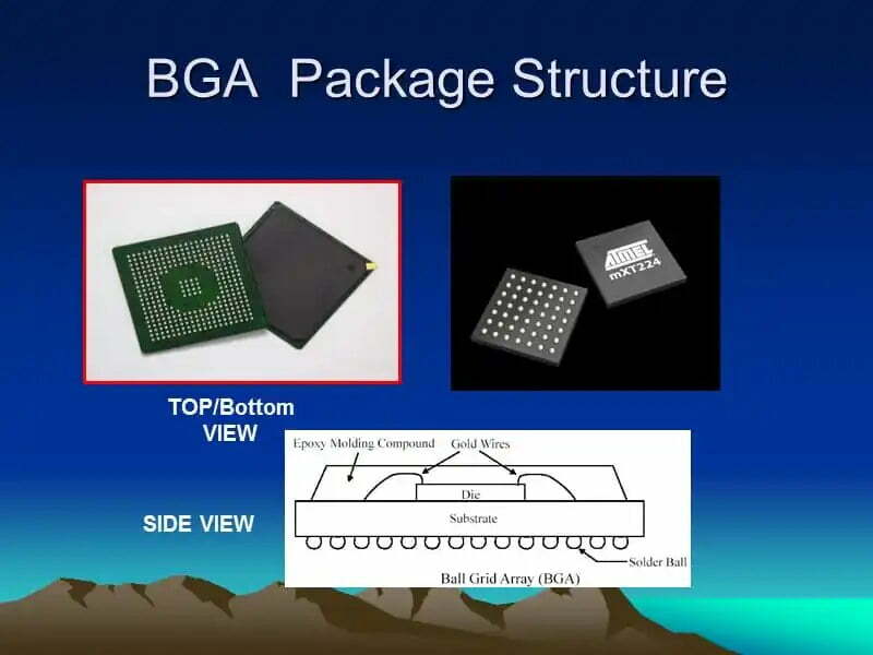
Trate a migração do símbolo e da pegada como uma tarefa de gerenciamento de dados, não uma limpeza cosmética. As bibliotecas Protel legadas geralmente contêm footprints duplicados, trocas de pin silenciosos ou nomeações que faziam sentido para um designer, mas não para compras ou montagem. Traga cada pacote de componente crítico de volta ao desenho do fabricante, especialmente conectores, BGAs, QFNs, pacotes com chumbo fino e peças de energia que dependem do volume de solda de almofadas expostas.
Se o produto ainda estiver sendo comprado em volume, alinhe a biblioteca migrada ao mesmo tempo. é aí que um disciplinado PCB Estrutura de bom assuntos. Uma migração do FootPrint que ignora os suplentes aprovados, sinalizadores de ciclo de vida e restrições de sourcing em nível de pacote apenas empurra a inconsistência downstream.
Construa o projeto Altium em torno dos pontos de verificação de verificação
O caminho de migração mais seguro é organizado. Importe o esquema e o PCB, resolva os links da biblioteca quebrados, recompile e compare o comportamento das regras e as saídas em pequenos pontos de verificação. Não espere até o final para regenerar tudo e espere que os deltas sejam aceitáveis.
No lado da PCB, inspecione o mapeamento de camadas, por meio de tipos, pontos de conservação, definições de sala, aviões divididos e derramamentos de cobre primeiro. Em seguida, mova-se para classes líquidas, regras de largura, regras de liberação, restrições de pares diferenciais e metas de comprimento. As regras antigas às vezes migram como padrões amplos, mesmo quando a placa original dependia de exceções locais mais restritas. Seções de potência de alta corrente, redes controladas por impedância e acesso ao ponto de teste são onde essa deriva se torna cara.
Os produtos de fabricação merecem uma comparação linha a linha
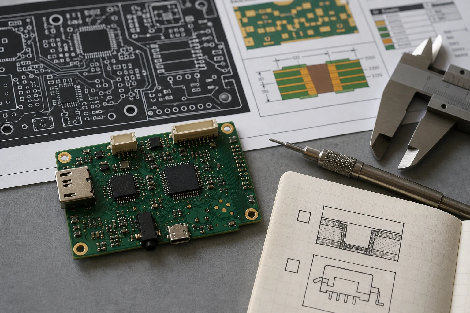
Depois que o design importado for compilado de forma limpa, gere as mesmas saídas de versão que a placa antiga usou. Compare contagens de brocas, uso de abertura, conteúdo de serigrafia, aberturas de máscara de solda, camadas de pasta e orientação do centroide. Se a placa migrada alimentar uma nova linha SMT ou um fluxo de trabalho diferente, confirme se o pacote de saída ainda é prático para o montador e não apenas com o valor CAD.
Esta etapa é fácil de subestimar. Uma placa pode passar na verificação de regras de design e ainda falhar na fabricação porque o novo contêiner de saída alterou a polaridade da camada, removeu detalhes mecânicos ou renomeou arquivos de forma a interromper a entrada automatizada das lojas. As equipes mais seguras comparam o novo pacote com o último comprovado da maneira como uma fábrica compara os dados recebidos, não a maneira como um designer olha um layout.
Onde os arquivos de assembly e as convenções do centróide foram alterados, revise-os com o mesmo rigor usado em um PCB Fluxo de processo de montagem. Isso evita que uma importação de CAD com sucesso se torne um problema de manufatura.
Saiba quando a migração deve se tornar redesenho
Alguns projetos da Protel não devem ser preservados exatamente. Se a placa já precisar de novos componentes, alvos de impedância revisados, espaçamento de creeage atualizado ou uma pilha de fabricação diferente, a conversão pode ser apenas a primeira etapa antes de um redesenho controlado. Nesses casos, o tempo de engenharia é melhor gasto, separando a intenção reutilizável da desordem legada.
Uma boa regra é esta: se seu esforço de verificação já está expondo soluções não documentadas, exceções de DFM não documentadas e bibliotecas desatualizadas, o conselho está dizendo que nunca esteve realmente sob controle de configuração. A conversão por si só não resolverá isso. Um redesenho parcial com bibliotecas mais limpas e saídas modernas pode ser um risco menor para o próximo ciclo de produção.
Uma lista de verificação prática de migração para placas de produção
- Congele o último pacote de fabricação aprovado antes de importar o design.
- Resolva bibliotecas de símbolos e espaços em relação a peças aprovadas atuais, não apenas a nomes legados.
- Reconstrua ou verifique as classes líquidas, as regras do par diferencial e as exceções especiais de liberação.
- Inspecione polígonos, conexões planas, configurações de alívio térmico e comportamento de manutenção após a importação.
- Regenere a fabricação, a montagem e as saídas de teste e compare-as com o pacote de lançamento histórico.
- Execute uma revisão piloto com as partes interessadas de fabricação ou montagem antes de usar o projeto Migrado para uma nova execução.
Conclusão
A migração do Protel to Altium Designer é bem-sucedida somente quando o novo projeto pode reproduzir a placa que sua fábrica sabe construir. Isso significa que o controle da biblioteca, a tradução de regras, a comparação de saída e a realidade de fabricação precisam concordar. Se sua equipe trata o trabalho como uma versão de engenharia estruturada em vez de uma conversão de software, o design migrado se torna útil. Caso contrário, o primeiro spin da placa se torna a auditoria que você deveria ter feito antes de pressionar Importar.
FAQ
O Altium Designer pode abrir arquivos antigos do Protel diretamente?
Muitas vezes sim, mas abrir o arquivo é apenas o início. Você ainda precisa verificar bibliotecas, regras de design, polígonos, mapeamentos de camadas e todas as saídas de fabricação antes de confiar no projeto migrado.
O que geralmente quebra primeiro em uma migração de Protel para Altium?
Links de footprint, regras personalizadas, despejos de cobre, classes de rede e trabalhos de saída são os pontos de falha comuns porque as estruturas de dados legadas raramente mapeiam um a um.
Você deve migrar as bibliotecas antes de liberar uma respin de placa?
Sim. Limpe as bibliotecas de símbolos e pegadas primeiro ou em paralelo com a importação de design. Caso contrário, cada correção de esquema ou layout se torna um patch único que é difícil de controlar posteriormente.
Quando o Reddraw é mais seguro que a conversão?
O Redraw geralmente é mais seguro quando os arquivos originais estão incompletos, as regras legadas não são documentadas ou o produto já precisa de Stackup, Footprint ou modernização de BOM.