PCB Schematic Design Software Recommendation
When selecting a PCB schematic design software, it is important to consider the features and capabilities of the particular software. Some of the most popular options for PCB schematic design software include Altium Designer, Autodesk Eagle, KiCad, OrCAD, and Proteus.
Altium Designer
Altium Designer is a powerful, feature-packed PCB design software with a wide range of features and capabilities. It is easy to use and has advanced automation tools, which makes it suitable for large and complex PCB designs. It also offers a comprehensive library of components and detailed analysis tools.
Autodesk Eagle
Autodesk Eagle is a popular choice for PCB schematic design. It offers an intuitive user interface and powerful schematic capture and PCB layout tools. It has a comprehensive library of components, 3D visualization, and powerful routing tools.
KiCad
KiCad is an open source PCB schematic design software available as a free download. It offers a wide range of features and capabilities, including schematic capture, PCB layout, and component library. It is easy to use and allows users to easily create professional-looking PCBs.
OrCAD
OrCAD is a powerful and feature-rich PCB design software. It has advanced features and capabilities, including powerful schematic capture and PCB layout tools, a library of components, and powerful simulation tools.
Proteus
Proteus is a popular choice for PCB schematic design software. It offers a wide range of features and capabilities, including a library of components, a powerful schematic capture tool, and advanced routing features. It is suitable for both simple and complex PCB designs.
PCB Schematic Design Process - Case Study
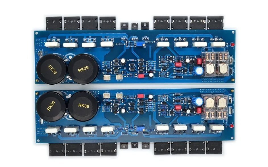
PCB schematic can helps an engineer understand how different components connect and what their functionalities are. All of this information is crucial when repairing or reproducing a PCB. Protel or Altium Designer are two programs you can use to create a netlist and schematic. After you have finished making the schematic, you will need to combine both sides of the board, arrange the paths, and assign symbols to the components. Below are all steps for designing and creating a circuit board schematics:
- Step 1: Create New PCB File
- Step 2: Setting Drawing Size
- Step 3: Setting Files Environment
- Step 4: Construct Schematic Library
- Step 5: Make Component Footprint
- Step 6: Place The Component Footprint on PCB File
- Step 7: Draw the Wiring
- Step 8: Adjust and Optimize Manually
- Step 9: ERC Checking
- Step 10: Generating Netlist According To PCB
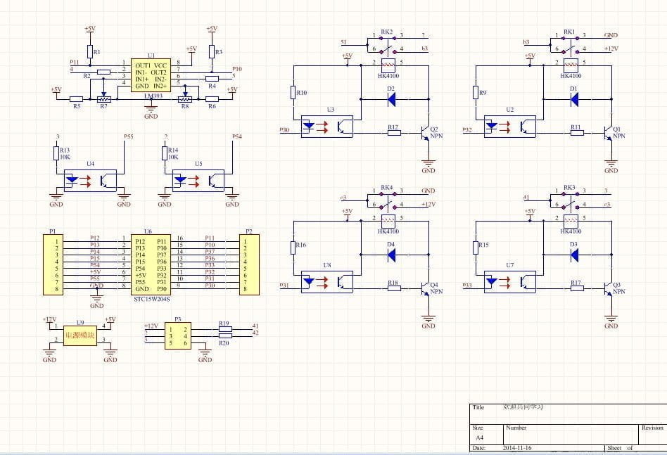
- Step 11: Drawing The Schematic
- Step 12: Checking and Optimizing Schematic
- Step 13: Output Schematic File
Step 1: Create a new PCB file
First, let’s open CAD or Protel, then click [File>>New] on the menu to create a new PCB file.

Step 2: Setting Drawing Size
You can choose A3 or A4 size drawings according to the complexity of the circuit. Single-page drawings is suitable for simple circuits, and multi-page drawings for complex circuits.

Step 3: Setting PCB Design Environment
Then we set the pcb environment parameters including: grid size, grid properties, cursor properties, drawing color, etc. The grid size should be synchronized with the schematic symbols.

Step 4: Create Schematic Library
Generally, there are built-in schematic library from pcb tools like Altium Designer or CAD, where you can enable schematic symbols . You can also create them manually basing the data sheet. Make sure that the pin names of the schematic symbols match those of the footprint library.

Step 5: Make Component footprint
Open the Library
Click [Library>>Components] in Protel to open the library, see the figure below:

Add components
There are two ways to add a component: one is to click “New” , the other is to click “Edit As” to modify the existing component to generate a new component. Either method will open a new window behind the Browse Libraries window to display the newly created component. At this time, close Browse Libraries to edit the new component, and save it after editing. (Remember the saving location of the component library.)
Step 6: Place The Component Footprint on PCB File
- 6.1. Reload the component library in QuickPCB (the modified library must be deleted and added again to see the new component footprint): Click F10 or the menu bar [Library >> Device] to open the Browser libraries window.
- 6.2. Run QuickPCB to open the front image as the base image: File >> Open Base Image >> Select the front image of the circuit board, and set the pixel size in the horizontal and vertical directions in the pop-up window (must be consistent with the scanning settings, otherwise Pictures vary in size).
- 6.3. At first, place the core components against the front side. Then, you need to mark important attributes such as withstand voltage, accuracy, and power. After, place test points on important signal lines.

Shortcut keys in QuickPCB:
pt: (press the p and t letters in sequence): place the connecting line;
pv: place vias;
pp: place the pad;
F10: place the component;
Ctrl+A: select all components;
Shift+click: to exclude the selection of the clicked object;
Tab: Press the Tab key when placing an element to open the properties dialog box, the most commonly used is to set the layer here;
Click a character (such as C3) when all components are selected: the character can be moved individually;
- 6.4. Save 8 kinds of files as top.b2p.
- 6.5. Re-open the reverse image as the base image.
- 6.6. Open the top.b2p file. The difference between this time and the picture in step 7 is that the base image has changed.
- 6.7. Select [Option>>Layer Setting] in the menu bar or F11 key to open the Layer Setting dialog box, remove the top layer in the circuit layer and silk screen layer, and return to the main window when the top layer component and silk screen are hidden but Vias are not hidden.
- 6.8. Place the components on the back side and align to the front side’s components. Then select the top layer in the circuit layer and silk screen layer in the layer settings.

- 6.9. Export PCB File: select [File>>Export as PCB file] in turn, and rename as “Instance Operation.pcb”.
Step 7: Draw the wiring
When drawing the pcb schematics, an engineer must have knowledge of power supply, circuit connection, PCB wiring, and so on in order to distinguish between ground wires, power wires, and signal wires. These circuits can be distinguished by looking at the way components are connected, the width of the copper foil on the circuit, and the properties of the electronic component itself. Below are some of pcb route rules:
- Avoid line crossing and interspersed.
- Grounding symbols can be used for grounding lines.
- Different colors can be used for various lines to ensure clear.
- Special signs can also be used for various components.
- Draw the unit circuits separately and combined them.
- Place the SMD components and connecting lines on the Top Layer layer.
- Place the vias on the Multi-Layer layer.
Step 8: Adjust and Optimize Manually
Manually check for duplicate, wrong connections. In addition, for resistance and capacitance components with larger tolerance, they can be packaged uniformly to reduce the cost of procurement and inventory management.

Step 9: Run ERC Checking
Check with the Electrical Rule Check (ERC) tool to make sure possible problems are fixed, such as signal connection errors.
Step 10: Generating Netlist According To PCB
The netlist is the key to successful PCB automatic routing. It serves as the bridge between schematic design and circuit board design. Unless the network table is populated, circuit boards cannot be wired. You can generate a netlist using the schematic design tool, or you can enter the PCB design system directly and access the parts footprint directly, bypassing the schematic design. You can also generate a netlist directly from the PCB design system, if the circuit version is relatively simple.
Import The PCB File Into Altium Designer

The unadjusted wiring and layout in QuickPCB can be adjusted here. (To turn off the Clearance check at this time: press the d and r keys in turn to open the setting dialog box, and uncheck the back of Clearance, as shown in the figure below.)

Create A Netlist
Select [Design>>Netlist>>Creat Netlist From Connected Copper] in the menu bar, and save the generated file as “netlist_file.html”.

There are two main parts in the network table:
					1. Component definition;
[
R1
0603
]

2. Network connection relationship;
(
UnNamedNet8
P1-2
U1-5
)
Note:
“[]” represents the start and end of the component definition, respectively;
“R1” is the component name;
“0603” is the footprint name;
“()” is the name of a network, followed by all the connection points on the network, such as the network connected to the 2Pin of P1 and the 5Pin of U1.
Configure The Netlist Of The PCB
Select the menu bar [Design>>Netlist>>Configure Physical Nets] in turn. The components and lines in the PCB appear to be connected before configuration, but the actual electrical relationship is not connected. So, they can they be truly connected together after be manipulated. At this time, a thin line can be seen by moving the components, as indicated by the yellow arrow in the following picture.


Step 11: Drawing The Schematic
11.1. Create a new schematic file, place all components and modify their names, footprints, etc. to be consistent with the corresponding components in “Instance Operation.pcb”.
11.2. Connect the schematic diagram in step 5.10.3 against the netlist generated in step 5.10.2.
11.3. Create a PCB project and add both “Instance Operation.pcb” and “Instance Operation.sch” to the project.
11.4. Execute [Design>>Update Sch…] in “Instance Operation.pcb” to check whether the names, comments, footprints, etc. of the components in the PCB and SCH files are consistent (if they are inconsistent, the schematic diagram needs to be modified).
11.5. Use Altium Designer 09 software to automatically compare the network connection relationship between PCB and SCH. If there is a difference, modify the schematic diagram until the two are the same.
11.6. Divide modules by function and readjust schematic layout.
Step 12: Checking and Optimizing Schematic
After drawing the schematic diagram, we need to check and optimize the nominal values of components that are sensitive to PCB distribution parameters. According to the PCB file diagram, the schematic diagram is compared, analyzed and checked to ensure that the schematic diagram and the file diagram are completely consistent. If it is found in the check that the layout of the schematic diagram does not meet the requirements, the schematic diagram will be adjusted until it is completely reasonable.
Step 13: Output Schematic File
Congratulations! You have completed the whole process! Now you can export the finished schematic file to PDF or other formats.
Common Errors to Avoid in PCB schematic design
There are a number of common errors that should be avoided when designing a printed circuit board (PCB) schematic.
First, it is important to ensure that all components are correctly labeled with their respective values, such as the resistor and capacitor values. This will help to avoid any confusion when troubleshooting or repairing the PCB in the future.
Second, ensure that all component footprints have been correctly specified. This includes making sure that the lead spacing, hole size, and other characteristics are correct for the component. Failing to do so could cause the component to not fit properly on the board, leading to potential failure.
Third, be sure to check the power supply specifications before attempting to layout the PCB. This includes the voltage and current requirements of each component, as well as the type of power supply that will be used. If these requirements are not met, the PCB may not function properly.
Fourth, pay attention to the component placement on the board. If components are placed too close together, they may interfere with one another, leading to poor performance. Additionally, if components are placed too far apart, this can lead to signal losses and cause the PCB to not function properly.
Finally, always double-check your work. Verify that all connections are correct, and make sure that all components are connected to the correct pins. Taking the time to check your work can save you time and money in the long run.
Conclusion
This guide from Reversepcb.com offers a comprehensive overview of the PCB schematic design process.
It covers the basics of schematic capture and the rules that must be followed during PCB routing, and provides best practices and tips for achieving a high-quality design. The guide also covers the tools and software commonly used in the industry for shecmatic design.
Whether you are new to PCB design or looking to improve your skills, this guide provides valuable information and guidance for designing high-quality printed circuit boards.
Related post: